Installation instructions Danfoss heat pump DHP-R Eco VMIFI102
Danfoss A/S is not liable or bound by warranty if these instructions are not adhered to during installation or service. The English language is used for the original instructions. Other languages are a translation of the original instructions.
Table of contents DHP-R Eco 1 Important information . . . . . . . . . . . . . . . . . . . . . . . . . . . . . . . . . . . . . . . . . . . . . . . . . . . . . . . . . . . 5 1.1 1.2 1.3 2 Refrigerant . . . . . . . . . . . . . . . . . . . . . . . . . . . . . . . . . . . . . . . . . . . . . . . . . . . . . . . . . . . . . . . . . . . . . . . . . . . . . 5 Noise and vibrations . . . . . . . . . . . . . . . . . . . . . . . . . . . . . . . . . . . . . . . . . . . . . . . . . . . . . . . . . . . . . . . . . . .
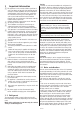
1 Important information ⚠ This appliance can be used by children aged from 8 years and above and persons with reduced physical, sensory or mental capabilities or lack of experience and knowledge if they have been given supervision or instruction concerning use of the appliance in a safe way and understand the hazards involved. Cleaning and user maintenance shall not be made by children without supervision. Children should be supervised to ensure that they do not play with the appliance.
1.3 Electrical connection ⚠⚠ The electrical installation must only be carried out by an authorized electrician (and must follow applicable local and national regulations). The electrical installation must be carried out using permanently routed cables. It must be possible to isolate the power supply using an all-pole circuit breaker for the intended current. For information regarding maximum load for externally connected devices, see electrical installation instructions.
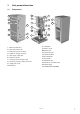
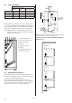
2 Heat pump information 2.1 Components 9 6 11 10 5 4 16 18 10 14 15 3 17 13 7 8 19 21 2 12 2 1 1 Coolant out (from HP) 2 Heat return (return line) 3 Return line hot-gas exchanger 4 Supply line hot-gas exchanger 5 Heat supply (supply line) 6 Coolant in (to HP) 7 Lead-in for communication cable 8 Lead-in for incoming supply and sensor 9 Supply pipe sensor 10 Condenser with draining for prim. side.
2.2 Pipe connections Connection diameter Brine DHP-R Eco 22 35 DHP-R Eco 26 35 DHP-R Eco 33 42 DHP-R Eco 42 42 Heat 28 28 28 28 35 35 300 mm De-superheater 300 mm 28 28 50 mm 500 mm When installing in confined spaces, pipe routing on the rear of the heat pump can be facilitated by connecting the pipes before the pump is put in position. See the figure below for an example on how the pipes can be routed.
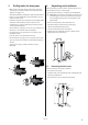
3 Drilling holes for brine pipes 4 • Make holes in the walls for the entry pipes (1) for the coolant pipes. Follow the dimensions and connection diagrams on pages 7-8. • The output and input coolant pipes must have wall lead-ins. • If there is a risk of infiltration by ground water, special lead-ins must be used. • Install the entry pipes (1) so that they incline slightly downwards. The incline should be at least 1 cm per 30 cm.
5 Piping installation 5.2 ⚠⚠ To prevent leaks ensure that there are no stresses in the connecting pipes! • Ensure that the pipe installation is carried out in accordance with the dimensions and connection diagrams. • Pipe installation must be carried out by an authorized installer. ⚠⚠ NOTE! It is extremely important that the heating system is completely bled. ⚠⚠ NOTE! Bleed valves must be installed where necessary. 5.1 Heating system supply pipe and return pipe • Install a filter (max mesh size 0.
6 Electrical Installation 6.1 Electrical connection ⚠⚠ The electrical installation must only be carried out by an authorized electrician (and must follow applicable local and national regulations). The electrical installation must be carried out using permanently routed cables. It must be possible to isolate the power supply using an all-pole circuit breaker for the intended current. For information regarding maximum load for externally connected devices. see electrical installation instructions.
6.4 Connecting hot water sensor • Auxiliary modules ⚠⚠ The two separate 24 VAC circuits must never be connected to each other or to protective ground. Hot water sensor PT1000 Connect the hot water sensor to the designated terminal block. The sensor should be positioned a third way up from the bottom in the water heater which is supplied with incoming cold water. See separate manual for the control system. 6.5 6.
6.14 Locations of the switches 7 Brine installation 7.1 Brine pipes and expansion tank • Install a filter (max mesh size 0.7 mm) in the input coolant pipe to protect the unit against foreign particles. • Install the input coolant pipe with all the accompanying components. • Install the output coolant pipe with all the accompanying components. • Supply both the pipes with diffusion sealed condensation insulation.
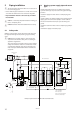
13 Stop both the pumps and immediately close valve 1 and 2. 14 Open valve 3 and disconnect the filling hoses. 15 Open valve 6 and pressurise the system, and vent via valve 1. Pressurise to max 1.5 bar. 16 Close valve 6. 17 Set switch S1 and S2 to Auto (compressor and brine pump). 18 Clean the strainers after filling. 8 Start up ⚠⚠ The installation may only start operation if the heating system, any hot water tanks and the coolant circuit are filled. Otherwise the pumps can be damaged.
9 Handover 9.1 Installation and commissioning carried out by: As user please ensure that the installer fills in the following information to facilitate servicing. PIPE INSTALLATION Date . . . . . . . . . . . . . . . . . . . . . . . . . . . . Company . . . . . . . . . . . . . . . . . . . . . . . . . . . . . . . . . . . . . . . . . . . . . . . . . . . . . . . . . . . . . . . . . . . . . . . . Name . . . . . . . . . . . . . . . . . . . . . . . . . . . Tel. No. . . . . . . . . . . . . . . . . . . . .
10 Troubleshooting Alarm In the event of an error message try restarting the installation using the reset button on the control panel. If restarting the heat pump does not help try rectifying the problem using the table below. Message Meaning Cause Remedy LOW PRESS ERROR Low pressure error - The compressor stops and there is no hot water production. Not enough anti-freeze in the coolant system. Air in the brine system. Blocked filter in the brine system.
Technical data DHP-R Eco 26 33 42 R410A 3.8 4.5 4.3 22 R410A 3.9 4.5 4.3 R410A 4.5 4.5 4.3 R410A 4.6 4.5 4.3 Scroll POE Scroll POE Scroll POE Scroll POE Volt kW kW A A 400 9,91 0.5 21.7 20 400 12,40 0.5 23.8 25 400 14,83 0.6 32.2 32 400 19,12 0.6 37.1 32 COP1 Heating capacity1 Electrical power1 kW kW 4.40 21.9 5.0 4.40 25.4 5.8 4.37 33.5 7.7 4.31 41.4 9.6 Nominal flow 2 Cooling circuit3 Heating circuit l/s l/s 1.4 0.5 1.5 0.6 2.1 0.8 2.4 0.
If these instructions are not followed during installation, operation and maintenance Danfoss Heat Pumps’ liability according to the applicable warranty is not binding. Danfoss Heat Pumps AB • Box 950 • SE-671 29 Arvika www.danfoss.