
Technical data


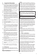
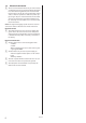
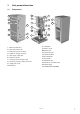
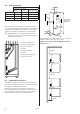
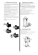
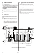
Table Of Contents

9
VMIFI102
3 Drilling holes for brine pipes
• Make holes in the walls for the entry pipes (1) for the
coolant pipes. Follow the dimensions and connection
diagrams on pages 7-8.
• The output and input coolant pipes must have wall lead-ins.
• If there is a risk of infiltration by ground water, special
lead-ins must be used.
• Install the entry pipes (1) so that they incline slightly
down-
wards. The incline should be at least 1 cm per 30 cm.
Cut them at an angle (as illustrated) so that rain water
cannot get into the pipes.
• Ensure that the entry pipes are at the correct distance so
that there is room for the other installations.
• Insert the brine pipes (2) into the insert pipes in the
installation room.
• Fill in the holes in the wall with mortar (3).
• Ensure that the brine pipes (2) are centred in the insert
pipes (1) so that the insulation is distributed equally on
all sides.
• Seal the insert pipes (1) with a suitable sealant
(foam) (4).
4 Unpacking and installation
The heat pump is packed in boxes and wrapped in card-
board and delivered on a wood pallet.
• Check that the delivery is complete and undamaged.
⚠
NOTE! When moving the heat pump, do not use the
protruding pipe connections to lift the heat pump.
The packaging should not be used to lift the heat
pump either.
• Move the heat pump to the installation site.
• Cut off the straps and remove the packaging.
• Lift the heat pump from the pallet.
• Install a condensation drain if required.
• Adjust using the adjustable legs (5) so that it stands
upright and level on the floor.
4.1 Removing the front cover
Remove the front cover plate as follows:
• Unscrew the screws (1).
• Slide the front cover (2) upwards and carefully lift it off
upwards and forwards.
• Place the front cover next to the heat pump.
5
5
1
2
5
5
1
2