FC 100/ 200/ 300 DeviceNet Contents Contents 1. Introduction 5 Safety Note 6 Assumptions 9 Hardware 9 Background Knowledge 9 Abbreviations 2. How to Install 11 13 Cabling 13 Installation of Option in the Frequency 17 3. How to Configure the System 19 Configure the Master 21 Configure the Frequency Converter 21 4.
Contents FC 100/ 200/ 300 DeviceNet Contents | Illustration 2 Illustration 1.1: 9 Illustration 2.1: 13 MG.33.D3.
FC 100/ 200/ 300 DeviceNet Contents Contents | Table Table 8.1: LED: Module Status (MS) 73 Table 8.2: LED: Network Status (NS) 74 MG.33.D3.
1. Introduction FC 100/ 200/ 300 DeviceNet 1 4 MG.33.D3.
FC 100/ 200/ 300 DeviceNet 1. Introduction 1. Introduction 1 1.1.1. Copyright, Limitation of Liability and Revision Rights This publication contains information proprietary to Danfoss A/S. By accepting and using this manual the user agrees that the information contained herein will be used solely for operating equipment from Danfoss A/S or equipment from other vendors provided that such equipment is intended for communication with Danfoss equipment over a PROFIBUS serial communication link.
1. Introduction 1 FC 100/ 200/ 300 DeviceNet 1.2.1. Safety Note The voltage of the frequency converter is dangerous whenever connected to mains. Incorrect installation of the motor, frequency converter or fieldbus may cause damage to the equipment, serious personal injury or death. Consequently, the instructions in this manual, as well as national and local rules and safety regulations, must be complied with. 1.2.2. Safety Regulations 1.
FC 100/ 200/ 300 DeviceNet 1. Introduction Also make sure that other voltage inputs have been disconnected, such as external 24 V DC, load sharing (linkage of DC intermediate circuit), as well as the motor connection for kinetic back up. 1 Please refer to the relevant Operating Instructions for further safety guidelines. MG.33.D3.
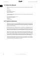
1. Introduction 1 FC 100/ 200/ 300 DeviceNet 1.3. About this Manual First time users can obtain the most essential information for quick installation and set-up in these chapters: Introduction How to Install How to Configure the System Application Examples For more detailed information including the full range of set-up options and diagnosis tools please refer to the chapters: How to Control the Frequency Converter How to Access the Parameters Parameters Troubleshooting 1.4.
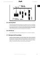
FC 100/ 200/ 300 DeviceNet 1. Introduction 1 Illustration 1.1: Topology 1.5. Assumptions These operating instructions assume that you are using a Danfoss FC 100, 200 or 300 frequency converter with DeviceNet. It is also assumed that as master you are using a PLC or PC equipped with a serial communication card supporting all the DeviceNet communication services required by your application.
1. Introduction 1 FC 100/ 200/ 300 DeviceNet 1.8. Available Literature The following literature is available for the FC 100, 200 and 300 series.
FC 100/ 200/ 300 DeviceNet 1. Introduction 1.9.
2. How to Install FC 100/ 200/ 300 DeviceNet 2 12 MG.33.D3.
FC 100/ 200/ 300 DeviceNet 2. How to Install 2. How to Install 2 2.1. Cabling 2.1.1. Cable Lengths Baud rate 125k baud 250k baud 500k baud Max total length cable Drop length Maximum per drop 500 meters (1640 ft.) 250 meters (820 ft.) 100 meters (328 ft.) 6 meters (20 ft.) for one drop Cumulative maximum 156 meters (512 ft.) 78 meters (256 ft.) 39 meters (128 ft.) 2.1.2. Cable Specifications The cable used should be according to ODVA specifications.
2. How to Install FC 100/ 200/ 300 DeviceNet 2.1.3. EMC Precautions The following EMC precautions are recommended in order to achieve interference-free operation of the DeviceNet network. Additional EMC information is available in the relevant FC 100, 200 or 300 Operating Instructions and Design Guides. 2 NB! Relevant national and local regulations, for example regarding protective earth connection, must be observed.
FC 100/ 200/ 300 DeviceNet 2. How to Install 2.1.4. Connection of the Cable Screen Danfoss recommends connection of the screen of the DeviceNet cable to ground at both ends of the cable at every DeviceNet station (see Danfoss recommendation for further details). Low impedance ground connection of the screen is very important, also at high frequencies. Achieve this by connecting the surface of the screen to ground, for example by means of a cable clamp or a conductive cable gland.
2. How to Install FC 100/ 200/ 300 DeviceNet 2.1.7. DeviceNet Connection It is essential to terminate the bus line properly. A mismatch of impedance may result in reflections on the line that will corrupt data transmission. The DeviceNet control card is provided with a plug-cable connector. When a plug connector is used as a splice between two trunk lines, the removal of devices will not sever the network. If required, strain relief must be provided by the developer.
FC 100/ 200/ 300 DeviceNet 2. How to Install 2.2. Installation of Option in the Frequency 2 To install a fieldbus option in the frequency converter you will need: - The fieldbus option - Fieldbus option adaptor frame for the frequency converter. This frame is deeper than the standard frame, to allow space for the fieldbus option beneath. - Cable holders Instructions: Remove the LCD panel from the frequency converter. - Remove the frame located beneath and discard. - Push the option into place.
3. How to Configure the System FC 100/ 200/ 300 DeviceNet 3 18 MG.33.D3.
FC 100/ 200/ 300 DeviceNet 3. How to Configure the System 3. How to Configure the System 3.1. Configure the DeviceNet Network 3 All DeviceNet stations that are connected to the same bus network must have a unique station address. The DeviceNet address of the frequency converter can be selected via: - Hardware switches (default 63) - Parameter 10-02 MAC ID (default 63) - Class code 0X03, Instance 1, Attribute 1 3.1.1.
3. How to Configure the System FC 100/ 200/ 300 DeviceNet 3.1.4. Baud Rate Setting All DeviceNet stations connected to the same bus network must have the same Baud rate. The baud rate of the frequency converter can be selected via: 3 - Hardware switches - Par. 10-01 Baudrate Select (default 125k Baud) - Object Class code 0x03, Instance 1, Attribute 2. 3.1.5.
FC 100/ 200/ 300 DeviceNet 3. How to Configure the System 3.2. Configure the Master 3.2.1. EDS File A large part area of the system configuration is the setting of application related parameters. EDS (Electronic Data Sheet) files simplify the setting up of most of the DeviceNet configurable parameters. Danfoss provides a generic English EDS file covering all voltage and power sizes, for offline configuration. The EDS file can be downloaded from http://www.danfoss.com/drives.
4. How to Control the Frequency Converter 4 22 MG.33.D3.
FC 100/ 200/ 300 DeviceNet 4. How to Control the Frequency Converter 4. How to Control the Frequency Converter 4.1. DeviceNet Process Control Modes This section describes two of three possible process control modes: Polling and Change of State (COS). The third FC control mode uses the acyclical mode Explicit Messaging via the Standard DeviceNet Control Supervisory object CLASS 29H.
4. How to Control the Frequency Converter FC 100/ 200/ 300 DeviceNet The figure below shows the different PCDs and their corresponding filter parameters. 4 Par. 10-20 to 10-23 can be used to filter out undesired events for COS. If a filter bit is set to 0, the corresponding I/0 Instance bit will be unable to produce a COS message. By default, all bits in the COS filters are set to 0.
FC 100/ 200/ 300 DeviceNet 4. How to Control the Frequency Converter 4.2. I/O Assembly Instances I/O Assembly Instances are a number of defined process control objects with defined content comprising control and status information. The figure below shows the I/O Assembly Instance options for controlling and monitoring the frequency converter. 4 4.3. Process Data Process data comprises the control and status data in the I/O Assembly Instances.
4. How to Control the Frequency Converter 4 26 MG.33.D3.
FC 100/ 200/ 300 DeviceNet 4. How to Control the Frequency Converter 4.4. ODVA Control Profile 4.4.1. Control Word under Instances 20/70 and 21/71 Control Word under Instances 20/70 and 21/71 Set par. 8-10 Control Word Profile to ODVA, and select the instance in par. 10-10 Process Data Type Selection. 4 The control word in Instances 20 and 21 is defined in the overview to the right: NB! Note that the bits 00 and 02 in Instance 20 are identical with bits 00 and 02 in the more extensive Instance 21.
4. How to Control the Frequency Converter FC 100/ 200/ 300 DeviceNet NB! Please note that changes will affect par. 8-50 to 8-56. Bit 6, Net Reference: Bit 6 = "0" Reference is from the standard inputs. Bit 6 = "1" Reference is from DeviceNet. 4 NB! Please note that changes will affect parameters 3-15 to 3-17 Reference source X. For the Speed reference, see section Bus Speed Reference Value under Instances 20/70 and 21/71. 28 MG.33.D3.
FC 100/ 200/ 300 DeviceNet 4. How to Control the Frequency Converter 4.4.2. Status Word under Instances 20/70 and 21/71 The status word in Instances 70 and 71 is defined in the overview to the right: NB! Note that the bits 00 and 02 in Instance 70 are identical with bits 00 and 02 in the more extensive Instance 71. Bit 00 01 02 03 04 05 06 07 08-15 4 Instance 70 Instance 71 Bit = 0 Bit = 1 Bit = 0 Bit = 1 Fault Fault Warning Running Running 1 Fwd 1 Fwd Running 2 Rev. Ready Ctrl from Net Ref.
4. How to Control the Frequency Converter FC 100/ 200/ 300 DeviceNet Bit 6, Ref from net: Bit 6 = "0" means that the reference comes from inputs to the drive. Bit 6 = "1" means that the reference comes from DeviceNet. Bit 7, At reference: Bit 7 = "0" means that the motor is running, but that the present speed is different from the preset speed reference, i.e. the speed is being ramped up/down during start/stop. Bit 7 = "1" means that the drive and reference speeds are equal.
FC 100/ 200/ 300 DeviceNet 4. How to Control the Frequency Converter 4.4.3. Bus Speed Reference Value under Instances 20/70 and 21/71 The speed reference value is transmitted to the frequency converter in the form of a 16bit word. The value is transmitted as a whole number. Negative figures are formatted by means of 2’s complement. The bus speed reference has the following format: 4 Par. 3-00 = "0" [refMIN -> refMAX] 0 (0000 Hex) [RPM] =>+ 32767 (7FFF Hex) [RPM] Par.
4. How to Control the Frequency Converter FC 100/ 200/ 300 DeviceNet 4.5. Danfoss FC Control Profile 4.5.1. Control Word under Instances 100/150 and 101/151 To select FC protocol in the control word, par. 8-10 Control Word Profile must be set to FC protocol [0]. The control word is used to send commands from a master (PLC or PC) to a slave (frequency converter).
FC 100/ 200/ 300 DeviceNet 4. How to Control the Frequency Converter Bit 02, DC brake: Bit 02 = ’0’ leads to DC braking and stop. Braking current and duration are set in par. 2-01 DC Brake Current and 2-02 DC Braking Time. Bit 02 = ’1’ leads to ramping. Bit 03, Coasting: Bit 03 = ’0’ causes the frequency converter to immediately "let go" of the motor (the output transistors are "shut off"), so that it coasts to a standstill.
4. How to Control the Frequency Converter FC 100/ 200/ 300 DeviceNet Bit 09, Selection of ramp 1/2: Bit 09 = "0" means that ramp 1 is active (parameters 3-40 to 3-47). Bit 09 = "1" means that ramp 2 (parameters 3-50 to 3-57) is active. Bit 10, Data not valid/Data valid: Is used to tell the frequency converter whether the control word is to be used or ignored. Bit 10 = ’0’ causes the control word to be ignored, Bit 10 = ’1’ causes the control word to be used.
FC 100/ 200/ 300 DeviceNet 4. How to Control the Frequency Converter 4.5.2.
4. How to Control the Frequency Converter FC 100/ 200/ 300 DeviceNet Bit 07 = ’1’ means that a warning has occurred. Bit 08, Speed ≠ reference/speed = reference: Bit 08 = ’0’ means that the motor is running, but that the present speed is different from the preset speed reference. It might, for example, be the case while the speed is being ramped up/ down during start/stop. Bit 08 = ’1’ means that the present motor present speed matches the preset speed reference.
FC 100/ 200/ 300 DeviceNet 4. How to Control the Frequency Converter 4.5.3. Bus Reference Value under Instances 100/150 and 101/151 The frequency reference value is transmitted to the frequency converter in the form of a 16bit word. The value is transmitted as a whole number (-32767 to 32767). Negative figures are formatted by means of 2’s complement. Master → slave 16 bit CTW Speed ref. RPM 4 The bus reference has the following format: 100% = 4000 Hex Par.
5. How to Access the Parameters FC 100/ 200/ 300 DeviceNet 5 38 MG.33.D3.
FC 100/ 200/ 300 DeviceNet 5. How to Access the Parameters 5. How to Access the Parameters 5.1. Explicit Messages DeviceNet is based on the CAN protocol. This means that every message contains an 11-bit CAN identifier field to define the connection ID. These CAN identifiers are also used to determine access priority. The MAC ID is stored in the header of the message, which is split into four different message groups.
5. How to Access the Parameters FC 100/ 200/ 300 DeviceNet 5.3.2.
FC 100/ 200/ 300 DeviceNet 5. How to Access the Parameters 5.3.5. Class ID 04h Assembly Object This is a standard DeviceNet Object for transfer of the I/O Instances (Process Data) described in the section “How to control the Frequency Converter”. Using this it is possible to send or read any of the defined Instances, either by polling or explicit messaging. The attributes supported for this class are listed below. 5.3.6.
5. How to Access the Parameters FC 100/ 200/ 300 DeviceNet 5.3.8.
FC 100/ 200/ 300 DeviceNet 5. How to Access the Parameters 5.3.9.
5. How to Access the Parameters FC 100/ 200/ 300 DeviceNet 5.3.10.
FC 100/ 200/ 300 DeviceNet 5. How to Access the Parameters The attributes supported are listed below.
5. How to Access the Parameters FC 100/ 200/ 300 DeviceNet 5.3.12. Class ID 10h Parameter Group Object This Object defines 14 parameter groups for all FC 100, 200 and 300 parameters. One Class instance exists for each parameter group. A read out of an instance will contain the name of the current parameter group. Group Instance 0 1 1 2 2 3 3 4 4 5 5 6 6 7 7 8 8 9 9 10 10 11 5 46 Name (max.
FC 100/ 200/ 300 DeviceNet 5. How to Access the Parameters 5.3.13. Class ID 28 Motor Data Object In this object, the current motor data can be configured and read out. The Instances, attributes and services supported for this class are listed below. 5.3.14.
5. How to Access the Parameters FC 100/ 200/ 300 DeviceNet 5.3.15. Class ID 29h Control Supervisory Object The Control Supervisory Object can be used for process control and monitoring of the frequency converter, as an alternative to the I/O Instances defined in the section “How to control the Frequency Converter”. The attributes supported for this class are listed below. 5.3.16.
FC 100/ 200/ 300 DeviceNet 5. How to Access the Parameters The State – Transition diagram below shows how the frequency converter will respond to the various command attributes associated with Class ID 0x29. 5 5.3.17. Class ID 2Ah AC/DC Drive Object Use this object to set and read out a range of FC 100, 200 or 300 drive control and status information. The attributes supported for this class are listed below. 5.3.18.
5. How to Access the Parameters FC 100/ 200/ 300 DeviceNet 5.3.19. Class ID 2Bh (Acknowledge Handler Object) Use this object to manage message reception acknowledgements, necessary for Change-Of-State support. The attributes supported for this class are listed below. 5.3.20.
FC 100/ 200/ 300 DeviceNet 5. How to Access the Parameters 5.5. Reading/Writing to Parameters with Index Indexed parameters such as 10-11 or 10-12 need special handling since DeviceNet does not support indexed addressing. The way to handle this in the frequency converter is to use par. 10-30 Parameter Data Types, which serves as an index pointer. Set up the pointer before each read/ write of an indexed parameter. NB! If two masters access this feature at the same time, incorrect data may be generated.
6. Parameters FC 100/ 200/ 300 DeviceNet 6 52 MG.33.D3.
FC 100/ 200/ 300 DeviceNet 6. Parameters 6. Parameters 8-01 Control Site Option: Function: [0] * Digital and ctrl. word Control by using both digital input and control word. [1] Digital only Control by using digital inputs only. [2] Control word only Control by using control word only. The setting in this parameter overrides the settings in par. 8-50 to 8-56.
6. Parameters FC 100/ 200/ 300 DeviceNet [3] Jogging [4] Max. Speed [5] Stop and trip [7] Select set-up 1 [8] Select set-up 2 [9] Select set-up 3 [10] Select set-up 4 Select the time-out function. The time-out function activates when the control word fails to be updated within the time period specified in par. 8-03 Control Word Time-out Time. 6 - Off [0]: Resume control via serial bus (Fieldbus or standard) using the most recent control word.
FC 100/ 200/ 300 DeviceNet [1] 6. Parameters Do reset Select Do reset [1] to return the frequency converter to the original set-up following a control word time-out. When the value is set to Do reset [1], the frequency converter performs the reset and then immediately reverts to the Do not reset [0] setting. Select Do not reset [0] to retain the set-up specified in par. 8-04, Select setup 1-4 following a control word time-out. This parameter is active only when Hold set-up [0] has been selected in par.
6. Parameters FC 100/ 200/ 300 DeviceNet NB! This parameter is active only when par. 8-01 Control Site is set to [0] Digital and control word. 8-52 DC Brake Select Option: Function: Select control of the DC brake via the terminals (digital input) and/or via the fieldbus. [0] 6 Digital input [1] Bus [2] Logic AND [3] * Logic OR NB! This parameter is active only when par. 8-01 Control Site is set to [0] Digital and control word.
FC 100/ 200/ 300 DeviceNet 6. Parameters Select Logic AND [2] to activate the Reverse command via the fieldbus/serial communication port, AND additionally via one of the digital inputs. Select Logic OR [3] to activate the Reverse command via the fieldbus/serial communication port OR via one of the digital inputs. NB! This parameter is active only when par. 8-01 Control Site is set to [0] Digital and control word.
6. Parameters FC 100/ 200/ 300 DeviceNet 8-90 Bus Jog 1 Speed Range: 100 RPM* Function: [0 - par. 4-13 RPM] Enter the jog speed. This is a fixed jog speed activated via the serial port or fieldbus option. 8-91 Bus Jog 2 Speed Range: 200 RPM* Function: [0 - par. 4-13 RPM] Enter the jog speed. This is a fixed jog speed activated via the serial port or fieldbus option. 10-00 CAN Protocol Option: 6 Function: [0] CANopen [1] * DeviceNet View the active CAN protocol.
FC 100/ 200/ 300 DeviceNet 6. Parameters 10-06 Readout Receive Error Counter Option: [0] Function: 0 - 255 View the number of CAN control receipt errors since the last power-up. 10-07 Readout Bus Off Counter Range: 0* Function: [0 - 255] View the number of Bus Off events since the last power-up. 10-10 Process Data Type Selection Option: Function: Select the Instance (telegram) for data transmission. The Instances available are dependent upon the setting of par. 8-10 Control Word Profile. When par.
6.
FC 100/ 200/ 300 DeviceNet 6. Parameters 16-04 Main Value [Unit] Actual 16-05 Main Actual Value (%) (Fixed) 16-10 Power [kW] 16-11 Power [hp] 16-12 Motor Voltage 16-13 Frequency 16-14 Motor Current 16-16 Torque 16-17 Speed [RPM] 16-18 Motor Thermal 16-19 KTY Sensor Temperature 6 16-21 Phase Angle 16-30 DC Link Voltage 16-32 BrakeEnergy/s 16-33 BrakeEnergy/2 min 16-34 Heatsink Temp. 16-35 Inverter Thermal 16-38 State 16-39 Temp.
6. Parameters FC 100/ 200/ 300 DeviceNet 16-68 Freq.
FC 100/ 200/ 300 DeviceNet 6. Parameters 34-54 Master Index Position 34-55 Curve Position 34-56 Track Error 34-57 Synchronizing Error 34-58 Actual Velocity 34-59 Actual Master Velocity 34-60 Synchronizing Status 34-61 Axis Status 34-62 Program Status Select the process read data for I/O Assembly Instances 101/151. Elements [2] and [3] of this array can be selected. Elements [0] and [1] of the array are fixed.
6. Parameters FC 100/ 200/ 300 DeviceNet Select the control source in Instance 21/71 and 20-70. [0] * Off Enables control via analog/digital inputs. [1] On enable control via the fieldbus. 10-20 COS Filter 1 Range: 0* Function: [0 - FFFF] Sets up the filter mask for the status word. When operating in COS (Change-Of-State), it is possible to filter out bits in the status word that should not be sent if they change.
FC 100/ 200/ 300 DeviceNet 6. Parameters - Store all set-ups: All parameter values will be stored in the nonvolatile memory. The value returns to Off when all parameter values have been stored. 10-33 Store Always Option: Function: [0] * Off [1] On This parameter is used to select whether parameter data received via the DeviceNet option should always be stored in nonvolatile memory.
6. Parameters FC 100/ 200/ 300 DeviceNet 6.2. Parameter List Par. No.
FC 100/ 200/ 300 DeviceNet 6. Parameters 6.3. Data Types Supported 6.3.1. Object and Data Types Supported Data types supported Data type 3 4 5 6 7 9 10 33 35 41 42 Description Integer 16 Integer 32 Unsigned 8 Unsigned 16 Unsigned 32 Visible string Byte string Standardized value (16 bit) Bit sequence Byte Word 6 6.3.2. Conversion Index This number refers to a conversion figure used when writing or reading to parameters. Conversion index 100 67 6 5 4 3 2 1 0 -1 -2 -3 -4 -5 -6 MG.33.D3.
7. Application Examples FC 100/ 200/ 300 DeviceNet 7 68 MG.33.D3.
FC 100/ 200/ 300 DeviceNet 7. Application Examples 7. Application Examples 7.1. Example: Working with Instance 101/151 Process This example shows how to work with I/O Instance 101/151, which consists of Control Word/Status Word and Reference/Main Actual Value. The Instance 101/151 also has two additional words, which can be programmed to monitor process signals, as shown in the figure.
7. Application Examples 7 FC 100/ 200/ 300 DeviceNet Parameter No.
FC 100/ 200/ 300 DeviceNet Output ad- 0.0-0.15 dress Set-up Control word 7. Application Examples 0.16-0.31 Reference 1.0-1.15 Not used 1.16-1.31 Not used 7 MG.33.D3.
8. Troubleshooting FC 100/ 200/ 300 DeviceNet 8 72 MG.33.D3.
FC 100/ 200/ 300 DeviceNet 8. Troubleshooting 8. Troubleshooting 8.1. Troubleshooting 8.1.1. LED Status First, check the LEDs. The DeviceNet control card contains two bi-colour (green/red) LEDs to indicate the state of the device and the network respectively. The upper LED indicates module status (MS). The lower LED indicates network status (NS).
8. Troubleshooting State No Power/Not on-line On-line, not connected On-line and connected Connection timeout Critical link failure FC 100/ 200/ 300 DeviceNet Bi-colour LED Off Green Green Red Status The option has not completed “Duplicate MAC ID” test yet or may not be powered. The option is on-line, but not allocated to a master. The DeviceNet option is on-line and connected to a master. One or more I/O connections are in timeout state. Red Table 8.2: LED: Network Status (NS) 8 74 MG.33.D3.
FC 100/ 200/ 300 DeviceNet 8. Troubleshooting 8.1.2. No Communication with the Drive If there is no communication with the drive, proceed with the following checks: Check 1: Is the cabling correct? Check that the cables are connected to the correct terminals as shown in the diagram. Colour Name 1 2 Terminal VCAN_L Black Blue 3 4 Drain CAN_H (bare) White 5 V+ Red GND CAN LOW Screen CAN HIGH +24 V Pin no.
8. Troubleshooting FC 100/ 200/ 300 DeviceNet 8.1.3. Drive Will Not Respond to Control Signals - Danfoss Control Word profile (instances 100/150 and 101/151) Check 1: Is the Control word valid? If bit 10=0 in the Control word, then the frequency converter will not accept the Control word, because the default setting is bit 10=1. Set bit 10=1 via the PLC. Check 2: Is the relationship between bits in the Control word and the terminal I/Os correct? Check the logical relationship in the frequency converter.
FC 100/ 200/ 300 DeviceNet 8. Troubleshooting The effect of control mode upon the function of par. 8-53 Start Select and 8-54 Reversing Se- lect: If Digital Input [0] is selected, the terminals will control the start and reversing functions If Bus [1] is selected, commands will be activated only when given via the control word. If Logic AND [2] is selected, both signals must be activated to perform the function. If Logic OR [3] is selected, activation of one signal will activate the function. Par.
8. Troubleshooting FC 100/ 200/ 300 DeviceNet If Bus [1] is selected, commands will be activated only when given via the control word. If Logic AND [2] is selected, both signals must be activated to perform the function. 8 If Logic OR [3] is selected, activation of one signal will activate the function. 78 Par. 8-55/56 setting: Bus [1] Terminal Bit 00/01, Function 13/14 Msb Lsb Msb Lsb Preset ref., Set-up no.
FC 100/ 200/ 300 DeviceNet 8. Troubleshooting 8.1.4. Alarm Word and Warning Word Alarm word and Warning word are shown on the display in Hex format. If there is more than one warning or alarm, a sum of all warnings or alarms will be shown. Alarm word and warning word can also be displayed using the field bus in par. 16-05, 16-06 and 16-04.
8. Troubleshooting Bit (Hex) 00000001 00000002 00000004 00000008 00000010 00000020 00000040 00000080 00000100 00000200 00000400 00000800 00001000 00002000 00004000 00008000 00010000 00020000 00040000 00080000 00100000 00200000 00400000 00800000 01000000 02000000 04000000 08000000 10000000 20000000 40000000 80000000 8 FC 100/ 200/ 300 DeviceNet FC 100/ 200/ 300 Warning word (Par.
FC 100/ 200/ 300 DeviceNet Index Index A Abbreviations 11 Alarm Word 79 Alarm Word, 16-90 65 Alarms 80 Array Index 10-30 64 B Bus Jog 2 Speed 58 C Cable Lengths 13 Cable Specifications 13 Change Of State, Cos 23 Coasting Select, 8-50 55 Connection Of The Cable Screen 15 Control Site, 8-01 53 Control Word Timeout Function 53 Conversion Index 67 D Danfoss Fc Control Profile 32 Danfoss Object Classes 50 Dc Brake Select, 8-52 56 Devicenet Connection 16 Devicenet Object Clas
Index FC 100/ 200/ 300 DeviceNet P Polling 23 Preset Reference Select, 8-56 57 Q Quick Stop Select 55 R Reset Control Word Timeout 54 S Safety Note 6 Setting The Devicenet Address 19 Setting The Devicenet Baud Rate 20 Start Select, 8-53 56 T Topology 9 V Vlt Parameters 21 W 82 Warning Parameter 10-13 63 Warning Word 79 Warning Word, 16-92 65 Warnings 80 MG.33.D3.