
Operating instructions


FC 100/ 200/ 300
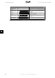
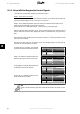
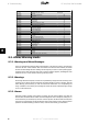
Bit (Hex) Warning word (Par. 16-92) Warning no.
00000001 Unused -
00000002 Drive over temperature 29
00000004 Earth fault 14
00000008 Unused -
00000010 Control word timeout 18
00000020 Over current 13
00000040 Torque limit 12
00000080 Motor thermistor over temp. 11
00000100 Motor ETR over temperature 10
00000200 Inverter overloaded 9
00000400 DC link under voltage 8
00000800 DC link over voltage 7
00001000 DC link voltage low 6
00002000 DC link voltage high 5
00004000 Mains phase loss 4
00008000 No motor 3
00010000 Live zero error 2
00020000 10 V low 1
00040000 Brake resistor power limit 26
00080000 Brake resistor short circuit 25
00100000 Brake chopper fault 27
00200000 Speed limit 49
00400000 Fieldbus comm. fault 34
00800000 24 V supply fault 47
01000000 Mains failure 36
02000000 Current limit 59
04000000 Unused -
08000000 Unused -
10000000 Unused -
20000000 Unused -
40000000 Unused -
80000000 Warning word 2 (ext. stat. word) -
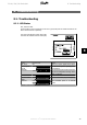
8.2. Alarm/Warning Limits
8.2.1. Warnings and Alarm Messages
There is a clear distinction between alarms and warnings. In the event of an alarm, The frequency
converter will enter a fault condition. After the cause for the alarm has been cleared, the master
will have to acknowledge the alarm message for the frequency converter to start operating again.
A warning on the other hand may come when a warning condition appears, and disappear when
conditions return to normal without interfering with the process.
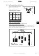
8.2.2. Warnings
All warnings within the frequency converter are represented by a single bit within a warning word.
A warning word is always an action parameter. Bit status FALSE [0] means no warning, while bit
status TRUE [1] means warning. To each bit and each bit status there is a corresponding text
string. In addition to the warning word message the master will also be notified through a change
of bit 7 in the Status Word.
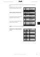
8.2.3. Alarms
Following an Alarm message, the frequency converter will enter Fault condition. Only after the
fault has been alleviated and the master has acknowledged the alarm message by setting bit 3 in
the Control Word, can the frequency converter resume operation. All alarms within the frequency
converter are represented by a single bit within an alarm word. An alarm word is always an action
parameter. Bit status FALSE [0] means no alarm, while bit status TRUE [1] means alarm.
8. Troubleshooting FC 100/ 200/ 300 DeviceNet
80
MG.33.D3.02 - VLT
®
is a registered Danfoss trademark
8