
Technical data


11
VMBMD302
6 Electrical Installation
6.1 Electrical connection
⚠
The electrical installation must only be carried out by
an authorized electrician (and must follow applicable
local and national regulations). The electrical instal-
lation must be carried out using permanently routed
cables. It must be possible to isolate the power sup-
ply using an all-pole circuit breaker for the intended
current. For information regarding maximum load
for externally connected devices. see electrical instal-
lation instructions.
Electrical current!
⚠
The terminal blocks are live and can be highly dan-
gerous due to the risk of electric shock. The power
supply must be isolated before electrical installation
is started. The heat pump is internally connected
at the factory. The electrical installation therefore
mainly covers the following points:
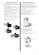
Connection to the power supply
• Remove the front cover from the heat pump.
• Pull the power supply cable through the opening in the
rear of the heat pump to the terminal blocks.
• Connect the supply cable to the designated terminal
block.
See separate manual for the control system.
⚠
Note that the power supply cable must only be con-
nected to the intended terminal block. No other ter-
minal blocks may be used!
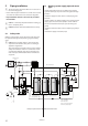
Electrical cabinet layout
K1 Contactor compressor
K2 Contactor brine pump
F10 Over current relay compressor.
F11 Over current relay brine pump
F1 Fuse brine pump
F2 Control fuse regulation. overheating protection
compressor
F3 Control fuse condensation pump
F100 Fuse 24 VAC 1
F101 Fuse 24 VDC
F102 Fuse 24 VAC 2
X1 Terminal blocks for incoming supply and tempera-
ture sensor as well as terminal blocks for external
components
T1 Transformer 24 VAC 2x50 VA
E1 WM HPC
E2 HPC RM
6.2 Connecting pump hot gas
Connect the hot gas pump to the designated terminal
block. The voltage is 230 VAC. The pump is designed to be
placed outside the heat pump casing and must be con-
nected with flexible hoses.
This pump runs in parallel with the compressor.
6.3 Connecting sensor for outside temper-
ature
Position the outdoor sensor on the north or north west
facing side of the house. away from direct sunlight. The
outdoor sensor should not be placed on reflective panel
walls. The sensor must be positioned at least 1 m from
openings in the walls that emit hot air.
If the sensor cable is connected through a pipe. the pipe
must be sealed so that the sensor is not affected by out-
going indoor air.
• Remove the rear piece from the heat pump.
• Route the outdoor sensor’s connecting cable through
the opening in the rear of the heat pump up to the con-
necting block.
• Connect the sensor to the designated terminal block.
See separate manual for the control system.
⚠
Note that the outdoor sensor is connected with
extra low protection voltage.
Also follow the applicable installation instructions for out-
door sensors!
NOTE! The bridge is
removed in the event
of separate control
circuit.
Bridged at delivery
Incoming cable
Incoming cable control circuit
T1
E1
E2
F1
F2
F3
F100
F101
F102
K2
K1
F11
F10
X1
Sensor outdoor
PT1000
Pump hot gas