
Technical data


13
VMBMD302
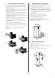
6.14 Locations of the switches
S1 Switch compressor. (Auto/Off )
S2 Switch coolant pump. (Auto/Off/Manual)
NOTE! Must only be used in manual position when fill-
ing the system or other maintenance/service work.
S3 Switch circulation pump. (Auto/Off/Manual)
6.15 Conversion table for sensors
When reading the resistance of the sensors, the sensor
leads must first be disconnected from the control equip-
ment.
First measure the sensor including the cable.
Then measure the sensor only.
7 Brine installation
7.1 Brine pipes and expansion tank
• Install a filter (max mesh size 0.7 mm) in the input cool-
ant pipe to protect the unit against foreign particles.
• Install the input coolant pipe with all the accompanying
components.
• Install the output coolant pipe with all the accompany-
ing components.
• Supply both the pipes with diffusion sealed condensa-
tion insulation.
• The expansion vessel for the coolant is sized according
to the manufacturer’s instructions.
• Max operating pressure heat source (see manufacturer’s
plate). Max 3 bar.
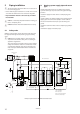
7.2 Filling the coolant system
⚠
WARNING! Ethylene glycol and ethanol must be han-
dled according to the instructions on the packaging!
1 Connect the hose from the filler pump to valve 1.
2 Connect the return hose to valve 2.
3 Close valve 3.
4 Open valves 1 and 2.
5 Mix coolant in container 4.
6 Ensure that the heat pump is not powered.
7 Start filling pump 5.
8 When the coolant flows out of the return hose the
internal coolant pump is bled inside the heat pump.
9 Set switch marked S1 in position Off. (Compressor
Auto/Off)
10 Switch on the heat pump’s safety switch.
11 Set switch marked S2 in position Manual. (Brine pump
Auto/Off/Manual)
12 Then let both the pumps operate until there is no air
mixture left in the circuit.
°C ohm
-30 882
-20 921
-10 960
0 1000
10 1039
20 1078
30 1117
40 1155
50 1194
60 1232
70 1270
80 1309
90 1347
100 1385
110 1422
120 1460
130 1497
1
2
3
4
5
6
S1
Auto
Off
S2
Auto
Off
Manual
S3
Auto
Off
Manual