Technical documentation | Air and ground source heat pumps Looking for support? Heat Pump Troubleshooting Guide Error phase sequence 02 Alarm communication 16 Working pressostat and high pressure pipe 03 Alarm Aux.
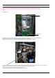
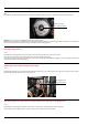
Troubleshooting Guide Error phase sequence The incoming phases have the incorrect sequence (only applies to 3-phase heat pumps). Action: Reset the phases Reset here option 1 or option 2 here When the compressor runs with the phases incorrectly sequenced a strange noise may be heard (loud, rattling). If the compressor for some reason runs backwards it cannot raise the temperature. When the compressor runs, check the discharge pipe temperature by feeling it with your hand.
Troubleshooting Guide Working pressostat and high pressure pipe The operating pressure switch does not close Switch off the main switch for the heat pump, wait until the compressor has been stationary for at least 10-15 minutes. Using the buzzer, check if the operating pressure switch is closed or not.
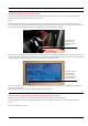
Troubleshooting Guide Working pressostat and high pressure pipe Hot gas temperature too high See in service under heat pump also check using own digital thermometer. Action: Check the refrigerant circuit see section below Discharge pipe sensor location The discharge pipe sensor displays correctly but still has high overheating Action: Using manometer apparatus and a digital thermometer check what the cooling and overheating reading of the unit is.
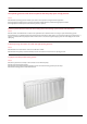
Troubleshooting Guide Alarm high pressure Blocked strainer in the heating system return Action: Shut off and clean the strainer on the return row Air in the heating system, outer jacket or in the Tws coil Action: Run the circulation pump in manual mode and listen for air. Switch between hot water and heating modes to check the whole heating system. Bleed the heating system according to the heat pump installation instructions.
Troubleshooting Guide Alarm high pressure Tip! Be careful not to spill water because there are electronics under the radiator pump; use something to protect the electronics. Nut for bleeding the circulation pump NOTE! This does not apply to the Optimum series of circulation pumps On Optimum one measures 0-10V (DC) at the molex switch (marked 0-10V) at the circulation pump while one runs it in a manual test. If there is no signal measure directly on the relay card terminals (See wiring diagram).
Troubleshooting Guide Alarm high pressure The operating pressure switch does not open but the heat pump opens at high pressure Action: Check that the operating pressure switch opens at the correct pressure, using manometer apparatus. If the high pressure switch opens at a lower pressure than indicated there is a fault in the high pressure switch If the high pressure switch opens at the incorrect pressure, replace it.
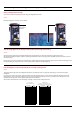
Troubleshooting Guide Alarm low pressure Blocked strainer on the brine circuit. Action: Check for brine in strainer (if necessary clean the strainer) Closed taps, main tap or filler cock on the brine circuit Action: Check that all taps are open, if not open them Air in the brine circuit Action: Start the brine pump in manual mode and listen for air in both the brine circuit and the heat pump.
Troubleshooting Guide Alarm low pressure Expansion valve defective or incorrectly set Action: Check that the cooling is correct for the specific heat pump model using manometer apparatus. Also check that the capillary tube is undamaged and that the bulb is correctly installed. Short active collector, e.g. short or dry bore hole, short surface soil collector Action: Check the length of the collector that is being used and compare with the collector length in the dimensioning documentation.
Troubleshooting Guide Alarm motor protection Phase drop or blown fuse Action: Check that all phases are present on the terminal block for incoming supply. If not, check the fuses in the cabinet and in the safety breaker for the heat pump. Also check that all wiring is secure. If screw terminals are used they must be properly tightened. If phoenix flat spring terminals are used, the cables must be secure in the correct hole with load on the cable.
Troubleshooting Guide Alarm motor protection Defective or incorrectly set motor protection Action: Use a hook-on ammeter to establish when the motor protection deploys, check what the motor protection is set to. Compare with table. To ensure that the alarm deploys ”mechanically” one can twin the red and the white cable that are marked 95-96 on the motor protection (see image).
Troubleshooting Guide Alarm circulation pump The circulation pump’s integrated alarm has deployed Action: Check if there is air in the heat transfer fluid circuit that can gather in the circulation pump Bleed the radiator circuit according to the installation instructions. Check if the circulation pump has jammed. If the circulation pump has jammed, there is an integrated shake function that attempts to shake itself loose up to a maximum of 5 times, if it does not succeed, an alarm will occur.
Troubleshooting Guide Alarm Brinepump The circulation pump’s integrated alarm has deployed Action: Check if there is air in the brine circuit that can gather in the circulation pump. Bleed the brine circuit according to the installation instructions. Check if the circulation pump has jammed. If the circulation pump has jammed, there is an integrated shake function that attempts to shake itself loose up to a maximum of 5 times, if it does not succeed, an alarm will occur.
Troubleshooting Guide Alarm brine Alarm Brine Action: Check the set value on ALARM BRINE in the heat pump’s control computer under service-heat pump-temperatures-alarm brine. Check that the brine sensor displays the correct value! See section sensor. The alarm is triggered when the temperature on BRINE OUT is as low or lower than the set value on ALARM BRINE. In the factory setting this function is inactive.
Troubleshooting Guide Alarm sensor Alarm sensor Action: Measure the resistance of the sensor, check the ohm value against the temperature according to the table below.. If the actual temperature and the temperature displayed do not correspond, calibrate or replace the sensor.
Troubleshooting Guide Alarm communication Alarm communication Action: Check if the communication between the display card and relay card is broken. Test with another TP cable or communication cable between display and control card If the alarm remains test with another I/O card using the old cable. Newer heat pumps with 901 921 display card (Control card) have all thinking/functions in the display.
Troubleshooting Guide Alarm Aux. heater Phase drop Action: Check that there is 230 V between incoming L2 on the circuit board and neutral on block 220. Check if the overheating protection has tripped. Check if any cables at the circuit board or overheating protection are loose or damaged. Check that the thin, gas filled wire to the bulb is intact. The overheat protection has tripped Action: Check if the overheat protection (T1) has tripped by pressing the red button until clicks.
Troubleshooting Guide Alarm Sound Whistling expansion valve Action: Try tapping gently on the expansion valve. Open and close the valve fully in and out and adjust the expansion valve to the recommended overheating. (Gas R134-404A 4-8 K, Gas R407C 4 K +-0,5K) Note! Manometer apparatus required! Check if the noise has stopped. If the problem persists, replace the expansion valve. Loud compressor noise Action: Check that there is 400V between incoming phases on the heat pump.
Troubleshooting Guide Alarm Sound The compressor’s IPR valve opens Action: When the valve opens, this is indicated by the pressure on the low pressure side rising and reaching the pressure of the high pressure side. Check at what pressure the valve starts to open. The compressor has an integrated IPR valve that opens at 28 ±3 bar. When the valve opens, pressure equalize between the compressor’s high and low pressure sides and a milling, whistling sound is heard.
Troubleshooting Guide Alarm Sound Touching pipes – vibrations Action: Establish which pipe(s) causes vibrations and try to remove the tension that is causing the vibrations by, for example, ensuring that no pipes or flexible hoses are too rigid, if that does not help one can install vibration damping rubber compensators on the vibrating pipe(s) Incorrectly installed flexible hoses - vibrations Action: All pipes should be routed in such a way that vibrations cannot be transmitted from the heat pump throug
Troubleshooting Guide Alarm Sound Vibrating protective sleeves on the pressure switches Action: Establish where the vibration noise occurs, if the vibration is in the protective sleeve one can prevent the vibration with insulating tape for example Vibration noise from the electrical installation Action: Check for electrical steps or similar devices screwed to the heat pump and wall. These can cause vibrations and noise.
Troubleshooting Guide Temperature or the quantity of hot water Defective 3-way valve motor Action: Check that the motor can be run to the limit positions in a manual test. If it is still, measure at the molex switch to see if there is current to it. Measure between 2 and 3 where there should always be 230V and between 2 and 6 where there should be 230V in switching mode If there is voltage replace the motor.
Troubleshooting Guide Temperature or the quantity of hot water Water heater too small in relation to requirement Action: Check the requirement and the water heater capacity. Replace with a larger heater or supplement with an extra heater if necessary.
Troubleshooting Guide Thermal comfort The house heating comfort is not adjusted to the customer’s requirements Action: Check the ROOM, CURVE and MIN settings. Adjust incorrect values in the heat pump’s control computer. ROOM = Desired indoor temperature CURVE = Should be set so that the desired indoor temperature is maintained regardless of the outdoor temperature. MIN = Lowest set-point value on the supply line regardless of the outdoor temperature, except with heat stop.
Troubleshooting Guide Thermal comfort Defective Honeywell 3-way valve Action: The motor should set the valve to the relevant end position depending on operating conditions. If it does not, hot water from the water heater will mix with the radiator water. Check the function of the 3-way valve motor by test running it manually. MANUAL TEST - REV.V. HOT WATER 0=Radiator mode, arm out from the valve. (terminal 6 no voltage) 1=Hot water mode, arm positioned towards the valve.
Troubleshooting Guide Thermal comfort Defective G2 shunt (HGW) Action: Check the function of the HGW shunt by test running it manually. If the motor does not shift mode during manual test operation, check that there is voltage to the motor. Terminal 221 brown/N (- signal open to RAD) 230Vac Terminal 222 black/N (+ signal open to HW) 230Vac Remember to measure with and without load.
Troubleshooting Guide Thermal comfort Basic setting G2 shunt + motor Action: Important to reset the shunt after taking the shunt apart! The groove of the white six edged sleeve must be towards 3 o’clock in unaffected mode. Adjust the motor as illustrated. Then screw the motor into place and press the knob to Auto mode. Manual mode when the button is not pressed in. Auto when the button is pressed.
Troubleshooting Guide High operating time additional heater Only runs on the additional heat Action: Ensure that the heat pump is not in additional heater only mode. If additional heater only mode is selected change to auto, the heat pump then regulates both the compressor and the additional heater. The compressor cannot run due to an alarm Action: Check the alarm that is indicated in the display. See chapter Alarm in the installation instructions or the fault tracing guide. Rectify the problem.
Troubleshooting Guide High operating time additional heater Incorrect flow in the brine circuit Action: Check the difference between the supply and return line using a digital thermometer. The difference should not be more than 4°C . A greater delta-t results in reduced efficiency in the heat pump. If the difference is greater than 4°C note what is causing it. Example: Dirt in the filter, system restrictions, system with high pressure drop.
Troubleshooting Guide Outdoor unit and defrosting problems Build-up of ice under and around the outdoor unit or water collecting Action: Drain the ground under and around the outdoor unit so that it can cope with the extra amount of water produced because of defrosting. During some periods when the outdoor unit is being defrosted, large amounts (20-40 L/day) of water can run off. One can also install a drip tray with a drainpipe routed to an indoor drain or gully.
Troubleshooting Guide Outdoor unit and defrosting problems Outdoor sensor/Defrost sensor Action: Check that the outdoor sensor/defrost sensor is installed according to the installation instructions and that it is correctly calibrated. Measure the ohms at the sensor to check it displays the correct value. temperature -30 -25 -20 -15 -10 -5 0 5 10 15 20 25 30 35 40 ohm 1884 1443 1115 868 681 538 428 343 276 224 183 150 124 103 86 Install according to the instructions and calibrate, if necessary.
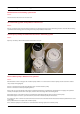
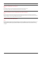
Troubleshooting Guide Room sensor digital Room sensor The image shows one of the models of room sensor available The room temperature sensor has a temperature sensor that provides a further value that the control system can use when calculating the supply temperature. The impact of the room sensor in the calculation can be set in the menu HEAT CURVE -> ROOM FACTOR. Default setting for ROOM FACTOR is 2 but can be adjusted from 0 (no impact) to 4 (large impact).
Troubleshooting Guide Electric hot water heaters Water does not get hot Action: Check fuse(s). Check if there is cold water supply, if not, check why and rectify the fault. Check if the overheat protection has tripped, reset by pressing the button until it clicks. Extremely long heating time Action: Check fuses so that all are intact at heaters with two phases or three phases. If not change fuse(s).
Danfoss Värmepumpar AB • 671 33 Arvika • Sweden • Tel.: + 46 570 813 00 • E-mail: heating@danfoss.com • heating.danfoss.com Danfoss can accept no responsibility for possible errors in catalogues, brochures and other printed material. Danfoss reserves the right to alter its products without notice. This also applies to products already on order provided that such alterations can be made without subsequential changes being necessary in specifications already agreed.