Application guidelines Danfoss scroll compressors SM SY SZ R22 - R407C - R134a - R404A - R507A - R513A - 50 - 60 Hz http://danfoss.us.
Application guidelines Content Compressor model designation...............4 Nomenclature............................................................. 4 Danfoss scroll compression principle......5 Features......................................................6 Technical specifications............................7 50 Hz data.................................................................... 7 60 Hz data.................................................................... 8 Dimensions......................
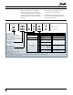
Application guidelines Compressor model designation Danfoss scroll compressors are available both as single compressors and as tandem units. The example below presents the single compressor nomenclature which equals the technical reference as shown on the compressor nameplate. Code numbers for ordering list are section “Ordering information & packaging”. For tandem and trio assemblies, please refer to the Danfoss Parallel Application Guidelines documentation FRCC.PC.005.
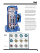
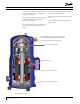
Application guidelines Danfoss scroll compression principle In a Danfoss SM / SY / SZ scroll compressor, the compression is performed by two scroll elements located in the upper part of the compressor. Suction gas enters the compressor at the suction connection. As all of the gas flows around and through the electrical motor, thus ensuring complete motor cooling in all applications, oil droplets separate and fall into the oil sump.
Application guidelines Features In addition to the existing SM range compressors previously available, Danfoss is completing its range with 3 compressors. The new SM112-124-147 and SZ147 compressors benefit from a further improved design to achieve the highest efficiency. Part protection and assembly reduces internal leaks and increases life durability. Improved part isolation reduces greatly acoustic levels. Gas intake design induces higher resistance to liquid slugging.
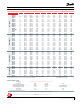
Application guidelines Technical specifications 50 Hz data R513A SINGLE R134a SINGLE R407C SINGLE R22 SINGLE Model SM084 SM090 SM100 SM110 SM112 SM120 SM124 SM147 SM148 SM161 SM175 SM/SY185 SY240 SY300 SY380 SZ084 SZ090 SZ100 SZ110 SZ120 SZ147 SZ148 SZ161 SZ175 SZ185 SY240 SY300 SY380 SZ084 SZ090 SZ100 SZ110 SZ120 SZ147 SZ148 SZ161 SZ175 SZ185 SY240 SY300 SY380 SZ148 SZ161 SZ175 SZ185 SY240 SY300 SY380 Nominal Cap. 60 Hz Nominal cooling capacity Power input TR W Btu/h kW 7 20400 69600 6.12 7.
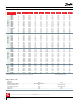
Application guidelines Technical specifications 60 Hz data R513A SINGLE R134a SINGLE R407C SINGLE R22 SINGLE Model Nominal Cap. 60 Hz Nominal cooling capacity Power input TR W Btu/h kW COP E.E.R. W/W Btu/h /W SM084 SM090 SM100 SM110 SM112 SM120 SM124 SM147 SM148 SM161 SM175 SM/SY185 SY240 SY300 SY380 SZ084 SZ090 SZ100 SZ110 SZ120 SZ147 SZ148 SZ161 SZ175 SZ185 SY240 SY300 SY380 7 7.5 8 9 9.5 10 10.5 12 12 13 14 15 20 25 30 7 7.
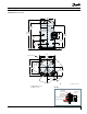
Application guidelines Dimensions SM/SZ 084-090-100-110-120 Ø 9.45 A: 18.29 B: 20.26 Ø 9.06 A: 20 B: 21.97 A: 15.02 B: 16.99 4.54 A: 9.92 B: 11.35 Ø 10 A: 11.60 B: 13.02 A: 5.59 B: 7.02 3.95 3.91 11.18 4 holes Ø 0.76 8.66 7.29 A: 6.42 B: 7.05 11.18 8.66 A: 6.17 B: 6.38 6.41 30° 3.89 45° All dimensions in inch A: SM/SZ 084-090-100 B: SM/SZ 110-120 Grommet HM 8 bolt Lock washer Flat washer Steel mounting sleeve Compressor base plate 1.
Dimensions Application guidelines SM 112-124-SM/SZ147* * except code 3 SM/SZ147 code 3 Ø 8.80 Ø 8.82 Ø 8.69 Ø 9.57 A: 21.06 B: 21.26 21.26 A: 10.84 B: 20.04 4.61 20.04 6.18 Ø 9.57 7.44 10.94 10.94 6.06 3.98 3.98 9.06 9.06 4 holes Ø 0.75 9.06 30 ° 7.09 7.5 7.5 4 holes Ø 0.75 7.5 9.06 30° 7.87 7.5 6.06 6.06 60 ° 6.81 60° 6.
Application guidelines SM/SZ 148-161 Dimensions SM 148-161 code 3 SM 148-161 code 4 Ø 10.47 Ø10.47 14.79 4.54 7.79 23.27 17.33 17.33 10.65 7.87 7.09 3.92 3.92 4 holes Ø 0.76 6.24 6.8 8.66 11.18 13.03 14.08 30° 7.36 8.23 3.89 7.32 8.66 11.18 All dimensions in inch Grommet HM 8 bolt Lock washer Flat washer Steel mounting sleeve Compressor base plate 1.
Application guidelines SM/SZ 175-185 & SY185 R and C version Dimensions Brazed version Rotolock version Ø 10.47 Ø 10.07 26.69 25.24 7.79 20.8 Ø 12.45 9.33 7.08 4.33 13.59 11 4 holes Ø 0.76 7.67 6.73 16.92 12 14.59 30° 9.38 7.75 6.57 7.08 7.95 7.32 7.36 All dimensions in inch Grommet HM 8 bolt Lock washer Flat washer Steel mounting sleeve Rubber grommet Nut 12 AB237986441643en-US0701 Compressor base plate 1.
Application guidelines Dimensions SM/SZ 185 P, X, Y version Brazed version Rotolock version Ø 10.47 Ø 10.47 Ø 10.07 Ø 10.07 25.55 24.17 7.36 25.59 24.21 7.36 20.80±0.04 20.80±0.04 8.46 8.46 6.02 153 77 3.18 Ø 12.48 6.02 3.26 3.07 Ø 12.48 3.26 3.18 SANS COMPRESSION: 1.16 / Without compression SANS COMPRESSION: 1.16 / Without compression AVEC COMPRESSION: 1.10 / With compression AVEC COMPRESSION: 1.10 / With compression 13.59 13.59 7.24 11 7.67 6.73 4 holes Ø 0.76 11 6.
Dimensions Application guidelines SY 240-300-380 Brazed version Rotolock version Ø13.54 Ø13.54 Discharge 1”1/8 Discharge A&B: 1”1/8 C: 1”3/8 A: 27.2±2 B: 67.63±2 C: 28.58 Ø13.11 Ø13.11 A: 24.33 B: 24.76 C: 25.71 A: 27.2±2 B: 67.63±2 7.36 A: 18.88±1.2 B: 19.31±1.2 C: 20.26±1.2 Suction A&B: 1”5/8 C: 2”1/8 7.7 3.43 187 A: 24.33 B: 24.76 A: 18.88±1.2 B: 19.31±1.2 Suction A: 1”1/2 B: 1”5/8 15.91 8.50 8.50 6.29 3.86 7.7 3.43 3.86 6.29 15.43 11.58 15.43 11.58 4 holes Ø0.
Application guidelines Dimensions Connection details Model SM/SZ084-090-100-110120-148-161 SM 112-124 SM/SZ 147 SM/SZ 175 - SM/SZ/SY185 SY 240 - 300 SY 380 Version V R-Y C-P-X AL MA - MB AA - AB AA - AB Suction and discharge connection brazed rotolock brazed brazed rotolock brazed brazed Oil sight glass threaded threaded threaded threaded threaded threaded threaded Oil equalisation connection 3/8" flare 3/8" flare 3/8" flare rotolock 1"3/4 1/2" flare 1/2" flare 1/2" fl
Application guidelines Electrical data, connections and wiring Motor voltage Danfoss SM / SY / SZ scroll compressors are available in five different motor voltages.
Application guidelines Electrical data, connections and wiring SY 240 – 300 – 380 & SM/SZ 185 - P, X, Y versions The terminal box is provided with 2 triple knockouts and 1 single knockout for power supply and 4 double knockouts for the safety control circuit. The 3 power supply knockouts accommodate the following diameters: • Ø 2 inch (UL 1"1/2 conduit) & Ø 1.72 inch (UL 1"1/4 conduit) & Ø 1.36 inch (UL 1" conduit) • Ø 1.59 inch (ISO40) & Ø 1.
Application guidelines Electrical data, connections and wiring Three phase electrical characteristics Compressor model Motor voltage code 3 200-230V/3 ph/60 Hz Motor voltage code 4 380-400V/3 ph/50 Hz 460V/3 ph/60 Hz Motor voltage code 6 230V/3 ph/50 Hz Motor voltage code 7 500V/3 ph/50 Hz 575V/3 ph/60 Hz Motor voltage code 9 380V/3 ph/60 Hz SM/SZ084 SM/SZ090 SM/SZ100 SM/SZ110 SM112 SM/SZ120 SM124 SM/SZ147 SM/SZ148 SM/SZ161 SM/SZ175 * SM/SZ185 * SY240 SY300 SM/SZ084 SM/SZ090 SM/SZ100 SM/SZ110 SM112
Application guidelines Electrical data, connections and wiring LRA (Locked Rotor Amp) Locked Rotor Amp value is the higher current as measured on mechanically blocked compressor tested under nominal voltage. The LRA value can be used as rough estimation for the starting current. However in most cases, the real starting current will be lower. A soft starter can be applied to reduce starting current. MMT (Max Must Trip current) The MMT is defined for compressors without their own motor protection.
Application guidelines Electrical data, connections and wiring Input controlled soft start When the control voltage is applied to A1 - A2, the MCI soft starter will start the motor, according to the settings of the ramp-up time and initial torque adjustments. When the control voltage is switched OFF, the motor will switch off instantaneously. MCI with bypass contactor By means of the built-in auxiliary contact (23-24) the bypass function is easily achieved, see wiring diagram below.
Application guidelines Electrical data, connections and wiring Compressor models SM / SZ 175 – 185 R and C version CONTROL CIRCUIT L1 L3 CONTROL CIRCUIT L2 L1 L3 Q1 Q1 F1 F1 KM F1 KA KA KA F1 KM KM KS KA KA KS KA F2 F2 LPS A3 180s HP KS T2 T1 T3 A1 A2 M T3 LPS A3 180s ThM TH LP T2 ThM A1 T1 L2 HP A2 M DGT DGT KS 1 KM KA 2 KS LLSV KS KM 1 TH KA 2 KS Wiring diagram without pump-down cycle Wiring diagram with pump-down cycle Compressor models SY 24
Application guidelines Electrical data, connections and wiring Motor protection The table below shows the protection method for the various compressors models.
Application guidelines Electrical data, connections and wiring If any thermistor exceeds its response temperature, its resistance increases above the trip level (4,500 Ω) and the output relay then trips -ie. contacts M1-M2 are open. After cooling to below the response temperature (resistance < 2,750 Ω), a 5 minute time delay is activated. After this delay has elapsed, the relay is once again pulled in ie. contacts M1-M2 are closed.
Application guidelines Electrical data, connections and wiring Compressor models SY240 to SY380 are delivered with an electronic module which provides protection against phase reversal and loss at start-up. Apply the recommended wiring diagrams. The circuit should be thoroughly checked in order to determine the cause of the phase problem before re-energizing the control circuit. The phase sequencing and phase loss monitoring functions are active during a 5 sec. window 1 sec.
Application guidelines Approval and certifications Approvals and certificates SM / SY / SZ scroll compressors comply with the following approvals and certificates. Pressure equipment directive 2014/68/EU Low voltage directive 2014/35/EU Machines directives 2006/42/EC Internal free volume Certificates are listed on the product datasheets: http://www.danfoss.
Application guidelines The scroll compressor application range is influenced by several parameters which need to be monitored for a safe and reliable operation. These parameters and the main recommendations for good practice and safety devices are explained hereunder.
Application guidelines Operating conditions Motor supply SM / SY / SZ scroll compressors can be operated at nominal voltages as indicated on page 18. Under-voltage and over-voltage operation is allowed within the indicated voltage ranges. In case of risk of under-voltage operation, special attention must be paid to current draw. Compressor ambient temperature SM / SY / SZ compressors can be applied from -31°F to 145.4°F (for SM/SZ084 to 185) and 127.4°F (for SY/SZ 240 to 380) ambient temperature.
Application guidelines Operating conditions SZ084 to 185 (except SZ147) R134a 160 150 Condensing temperature (°F) 140 S.H. = 20°F 130 S.H. = 54°F SUPERHEAT 120 110 100 90 80 0 10 20 30 40 50 60 70 Evaporating temperature (°F) SZ147 R134a 160 S.H. = 20°F Condensing temperature (°F) 150 140 130 120 110 100 90 80 0 10 20 30 40 50 60 70 Evaporating temperature (°F) SY240 to 380 R134a 160 Condensing temperature (°F) 150 140 S.H. = 20 °F 130 S.H.
Application guidelines Operating conditions SY240 to 380 R513A 167 158 149 SH=10K Condensing temperature (°F) 140 S.H. = 30 K 131 122 113 104 93 86 77 68 59 -13 -4 5 14 23 32 41 50 59 68 Evaporating temperature (°F) SZ148-185 / SY185 R513A 167 158 Condensing temperature (°F) 149 SH=10K 140 131 SH=30K 122 113 104 93 86 77 68 59 -13 -4 5 14 23 32 41 50 59 68 77 86 Evaporating temperature (°F) SZ084 to 185 R404A / R507A 150 140 Condensing temperature (°F) 130 S.H.
Application guidelines Operating conditions SZ084 to 185 & SY185 R407C at DEW temperature Dew temperature conditions 160 150 Condensing temperature (°F) 140 130 120 S.H. = 54 °F SUPERHEAT S.H. = 20°F 110 100 90 80 -10 0 10 20 30 40 50 60 70 Evaporating temperature (°F) Dew temperature conditions SY240 to 380 R407C at DEW temperature 160 150 Condensing temperature (°F) 140 130 S.H. = 20°F 120 S.H.
Application guidelines Operating conditions Dew temperature and mean temperature for R407C pressure (log) Mean Dew Mean Dew enthalpy The following operating diagrams show the difference between mean and dew temperature application envelopes. Dew temperature Dew temperature conditions 160 Example for SZ 084 to 185 150 Condensing temperature (°F) 140 130 120 S.H. = 54 °F SUPERHEAT S.H.
Application guidelines Operating conditions Discharge temperature protection The discharge gas temperature must not exceed 275°F. The discharge gas thermostat accessory kit (code 7750009) includes all components required for installation, as shown below. The thermostat must be attached to the discharge line within 150 mm from the compressor discharge port and must be thermally insulated and highly fixed on the pipe.
Application guidelines Operating conditions Internal pressure relief valve The SY240 to SY380 incorporate an internal relief valve set to open between the internal high and low pressure sides of the compressor when the pressure differential between the discharge and suction pressures surpasses 450 to 551 psi. HP This safety feature prevents the compressor from developing dangerously high pressures should the high pressure cutout, for whatever reason, fail to shut down the compressor.
Application guidelines System design recommendations General Successful application of scroll compressors is dependent on careful selection of the compressor for the application. If the compressor is not correct for the system, it will operate beyond the limits given in this manual. Poor performance, reduced reliability, or both may result.
Application guidelines System design recommendations Refrigerant charge limit Danfoss SM / SY / SZ compressors can tolerate liquid refrigerant up to a certain extend without major problems. However, excessive liquid refrigerant in the compressor is always unfavorable for service life. Besides, the installation cooling capacity may be reduced because of the evaporation taking place in the compressor and/or the suction line instead of the evaporator.
Application guidelines System design recommendations Sump heater The surface sump heaters are designed to protect the compressor against off cycle migration of refrigerant. When the compressor is idle, the oil temperature in the sump of the compressor must be maintained at no lower than 18°F above the saturation temperature of the refrigerant on the low-pressure side. This requirement ensures that the liquid refrigerant is not accumulating in the sump.
Application guidelines System design recommendations stored in the condenser during pump-down if all components have been properly sized. Other application needs a liquid receiver to store the refrigerant. Liquid flood back During normal operation, refrigerant enters the compressor as a superheated vapor. Liquid flood back occurs when a part of the refrigerant entering the compressor is still in liquid state. Danfoss SM/SY/SZ scroll compressors can tolerate occasional liquid flood back.
Application guidelines Specific application recommendations Low ambient application Low ambient start-up Under cold ambient conditions (<32°F), upon start-up the pressure in the condenser and, if present, the receiver may be so low that a sufficient pressure differential across the expansion device cannot be developed to properly feed the evaporator. As a result, the compressor may go into a deep vacuum, which can lead to compressor failure due to internal arcing and instability in the scroll members.
Application guidelines Specific application recommendations Sump heaters Sump heaters are strongly recommended on all systems where the compressor is exposed to low ambient temperatures, especially split and remote condenser installations. The sump heater will minimize refrigerant migration caused by the large temperature gradient between the compressor and the remainder of the system, please refer to section “Off-cycle migration”.
Application guidelines Specific application recommendations Sump heaters Sump heaters are mandatory on reversible cycle applications given the high probability of liquid migration back to the compressor sump during off-cycles due to the outdoor location of most units and operations during low ambient conditions. Discharge temperature thermostat Heat pumps frequently utilize high condensing temperatures in order to achieve a sufficient temperature rise in the medium being heated.
Application guidelines Specific application recommendations Suction line accumulator The use of a suction line accumulator is strongly recommended in reversible cycle applications as a result of the possibility of a substantial quantity of liquid refrigerant remaining in the evaporator, which acts as a condenser during the heating cycle.
Application guidelines Sound and vibration management Starting sound level During start-up transients it is natural for the compressor sound level to be slightly higher than during normal running. SM / SY / SZ scroll compressors exhibit very little increased start-up transient sound. If a compressor is miswired, the compressor will run in reverse. Reverse compressor rotation is characterized by an objectionable sound.
Application guidelines Sound and vibration management Compressor sound radiation For sound radiating from the compressor, the emission path is airborne and the sound waves are travelling directly from the machine in all directions. The Danfoss SM / SY / SZ scroll compressor is designed to be quiet and the frequency of the sound generated is pushed into the higher ranges, which not only are easier to reduce but also do not generate the penetrating power of lower-frequency sound.
Application guidelines Compressor handling and storage Installation Each SM / SY / SZ compressor is shipped with printed Instructions for installation. These instructions can also be downloaded from our web site: www.danfoss.com or directly from: http://instructions.cc.danfoss.com Each Danfoss SM / SY / SZ scroll compressor is equipped with two lift rings on the top shell. Always use both these rings when lifting the compressor. Use lifting equipment rated and certified for the weight of the compressor.
Application guidelines Installation Mounting of SY 240-300-380: the required bolt size is HM10. The minimum required flat washer outside diameter is 20 ft.lbs. Mounting bolts must be tightened to a torque of 30 ft.lbs. These bolts and washers are not supplied with the compressor. Note: The large flat washer must be positioned in place before shipping the unit with the compressor installed. Lock washer * Large flat * 1.06 inch washer HM 10 Bolt * Compressor base plate Steel mounting sleeve 1.
Application guidelines Installation Copper to copper connections When brazing copper-to-copper connections, the use of a copper / phosphorus brazing alloy containing 5% silver or more with a melting Dissimilar metals connection When manipulating dissimilar metals such as copper and brass or steel, the use of silver solder and anti-oxidant flux is necessary.
Application guidelines Installation System pressure test Always use an inert gas such as nitrogen for pressure testing. Never use other gasses such as oxygen, dry air or acetylene as these may form Maximum compressor test pressure (low side) an inflammable mixture.
Application guidelines Installation Filter driers A properly sized & type of drier is required. Important selection criteria include the driers water content capacity, the system refrigeration capacity and the system refrigerant charge. The drier must be able to reach and maintain a moisture level of 50 ppm end point dryness (EPD). For new installations with SM/SY/SZ compressors with polyolester oil, Danfoss recommends using the Danfoss DML (100% molecular sieve) solid core filter drier.
Application guidelines Installation Commissioning The system must be monitored after initial startup for a minimum of 60 minutes to ensure proper operating characteristics such as: • Proper metering device operation and desired super heat readings, • Suction and discharge pressure are within acceptable levels, • Correct oil level in compressor sump indicating proper oil return, Oil level checking and top-up In installations with good oil return and line runs up to 66 ft, no additional oil is required.
Application guidelines Ordering information & packaging Packaging Single pack Compressor models Length in Width in Height in Industrial pack Gross weight lb Nbr* Length in Width in Height in Gross weight lb Static stacking pallets SM/SZ084 22.2 18.5 26.4 165 8 44.9 37.4 27.8 1213 3 SM/SZ090 22.2 18.5 26.4 168 8 44.9 37.4 27.8 1248 3 SM/SZ100 22.2 18.5 26.4 168 8 44.9 37.4 27.8 1248 3 SM/SZ110-120 22.2 18.5 29.5 187 8 44.9 37.4 29.8 1407 3 SM112 22.
Application guidelines Ordering information & packaging SM-SY Single Compressor model Connections Motor protection 3 Code no.
Application guidelines Ordering information & packaging SM-SY Industrial Compressor model Connections Motor protection Code no.
Application guidelines Ordering information & packaging SZ Single Compressor model Connections Motor protection 3 Code no.
Application guidelines Ordering information & packaging SZ Industrial Compressor model Connections Code no.
Application guidelines Accessories Solder sleeve adaptator set Application Packaging Pack size 7765005 Solder sleeve adapter set (1"3/4~1"1/8), (1"1/4~3/4") SM/SZ084-090-100 Multipack 6 120Z0405 Solder sleeve adapter set (1"3/4~1"3/8), (1"1/4~7/8") SM110-112-120-124-148-161 & SM/SZ147 & SZ110-120-148-161 Multipack 8 7765006* Solder sleeve adapter set (1"3/4~1"3/8), (1"1/4~3/4") SM110-112-120-124-148-161& SM/SZ147 & SZ110-120-148-161 Multipack 6 SM/SZ175-185, SY 240-300 Multipack 6 Appli
Application guidelines Accessories Rotolock nuts Type Code n° Description 8153123 Rotolock nut,1"1/4 8153124 Rotolock nut,1"3/4 8153126 Rotolock nut,2"1/4 Pack size Application Packaging Models with 1"1/4 rotolock connection Models with 1"3/4 rotolock connection Models with 2"1/4 rotolock connection Multipack Multipack Multipack Application Packaging Pack size SM / SZ084 to 100 - 110* to 161* SM / SZ110 to 161 SY / SM / SZ175/185* SY / SM / SZ175/185 SY240 - 300 Multipack Multipack Multipack
Application guidelines Accessories Discharge temperature protection Type 7750009 Discharge thermostat kit All models Multipack Pack Size 10 7973008 Discharge thermostat kit All models Industry pack 50 Packaging Pack Size Single pack 1 8156147 Mounting kit for scroll compressors. Grommets, sleeves, SM/SZ084-090-100-110-120-148-161-175bolts, washers 185 Mounting kit for scroll compressors.
Application guidelines Accessories Terminal boxes, covers & T-block connectors Type Code No Description Application Packaging Pack Size SM/SZ148-3.161-3.175.185 Single pack 1 SM/SZ147-3 Single pack 1 8156139 Terminal box 7.3 x 7.8 inch, incl cover 120Z0413 Terminal box cover 8156135 Service kit for terminal box 3.8 x 4.5 inch, including 1 cover, 1 clamp, 1 T block connector 2 x 2.2 inch SM084.090.100.110.112.120.124.14 7.148.161 (except SM148-3.161-3) & SZ084.090.100.110.120.148.
Danfoss Commercial Compressors is a worldwide manufacturer of compressors and condensing units for refrigeration and HVAC applications. With a wide range of high quality and innovative products we help your company to find the best possible energy efficient solution that respects the environment and reduces total life cycle costs.