
Operating instructions

Instruction SONO 1500 CT
DEN-SMT/PL VI.SH.K1.02 Danfoss District Enrgy
2
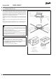
Depending on the application (heat or cooling meter), the ow sen-
sor is installed in the forward or return pipe of the system. The ow
sensor must be installed so that the direction of ow corresponds
to the direction of the arrow on the sensor. Calming sections are not
needed before or after the energy meter, but calming sections of
3xDN are recommended before the meter.
The ow sensor can be installed in both horizontal and vertical pipe
sections, but every time so that air bubbles cannot collect in the ow
sensor.
The ow sensor must always be lled with water. Avoid frost on the
meter.
We recommend installing the ow sensor in a tilted (45°) position.
The minimum system pressure must be 1 bar to avoid cavitation.
Make sure the ow sensor is installed suciently far away from
possible sources of electromagnetic interference (switches, electric
motors, uorescent lamps, etc...).
To simplify the removal of the ow sensor it is recommended to
install isolating valves before and after the meter.
The ow sensor should be installed in an accessible position for
service and operating personnel.
Initial operation is to be carried out and recorded after installation.
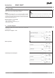
Use unsealed ow sensors (Flow sensor for heating):
- at water temperatures permanently above ambient temperatures
Use sealed ow sensors (Flow sensor for cooling):
- for cold applications or T
water
< T
ambient
- if permanent condensation is expected
3.0 Installation of ow sensor
5 ... 130 / 150 °C *
5 ... 105 °C **
5 ... 130 °C *
5 ... 90 °C **
* External supply
** With battery supply