
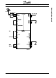
Technical data

9
MG.10.Q1.5B – VLT is a registered Danfoss trade mark
VLT 5000/5000 FLUX SyncPos Quick-Setup
Function of inputs and output must be selected in
parameter group 3xx according to the required
functions. Note that the default values are different
from a drive without option.
Please note that Dead Time Compensation in
parameter 780 (not Flux) is set to OFF. This para-
meter is to prevent oscillation at standstill.
■■
■■
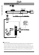
■ Checking encoder connection and direction of
rotation
If you have not yet done so, now is the time to
connect and test the encoder. In this example it is
assumed an incremental encoder is used.
NB!
Remember to turn off the power before
connecting the encoder. See "Technical
Data/Wiring examples" for encoder wiring.
Preparation for first run
To be able to communicate with the SyncPos option
please observe the application example regarding
the wiring of the RS 232 to 485 converter.
Please note that outputs of both the VLT and
SyncPos may change, hence control of mechanical
brake or such may be interrupted.
Next, there are only 2 important parameters for
testing the encoder connection and rotation. One is
the Proportional gain factor of the SuncPos PID
loop. This parameter is accessible via the LCP
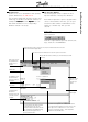
parameter 702. The other is the encoder resolution
parameter (ENCODER). To access the ENCODER
parameter click "CONTROLLER", "PARAMETERS",
and "AXIS".
Press "ok" to confirm interruption of program.
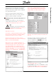
Choose parameter group Encoder. The factory
default setting of encoder resolution is 500 as
shown.
Enter the correct value in pulses per revolution and
press ok.
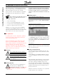
Check the encoder connections by means of the
encoder test program. In the menu bar click on
"FILE" and "OPEN" the file
Enc-S.mEnc-S.m
Enc-S.mEnc-S.m
Enc-S.m, which is the
first test program for starting operation.
First set parameter 700 = "2". In the
"DEVELOPMENT"
menu click on "EXECUTE"
in order
to start the test program or press F5. The position 0 is
registered in the communications window.Run the
Checking encoder connections