
Operating instructions

VLT
®
2800, VLT
®
6000 HVAC and VLT
®
8000 AQUA Modbus RTU
■ Installation and Setup
Modbus RTU is a transmission protocol developed for
process control systems. The Modbus standard does
not specify the physical interface for the protocol i.e.
a number of different interfaces can be chosen.
The Modbus RTU protocol is based on the build-in
RS-485 (EIA-485) interface.
RS-485 is a two-wire bus-interface that allows
multi-drop network topology i.e. nodes can
be connected as a bus, or via drop cables
from a common trunk line.
A total number of 32 nodes can be connected to
one Modbus RTU network segment, and a total of
247 nodes in a network are supported.
Network segments are divided with repeaters.
Please note that each repeater counts for a node
in each segment it’sinstalled.
Every node connected to the same network must have
an unique nodes address, across all segments.
Every segment must be terminated in both ends,
either with the termination switches (switch 2 &
3) of the VLT 6000 / VLT 8000 or with a biased
termination resistor network.
For bus-cabling always use cable of screened
twisted pair type (STP), and make sure to follow
good common installation practice.
Make sure the screen of the Modbus RTU cable must
always be connected to ground at all nodes.
It is very important to have a low impedance ground
connection of the screen, also at high frequencies.
This can be obtained by connecting a large surface
of the screen to ground, for example by means of
a cable clamp or a conductive cable gland.
Particularly in installation where there is long
cable lengths, it can be necessary to apply
potential equalizing cables to ensure same ground
potential throughout the network.
To prevent impedance mismatch, always use cable
of same type across the entire network.
When connecting a motor to the frequency converter,
make sure always to use screened motor cable.
Address range:
1-247
Baud Rate:
300 - 9600 bps
Cable:
Screened twisted pair (STP)
Impedance: 120 Ohm
Cable length:
Max. 1200 m (including drop lines)
Max. 500 m station-to-station
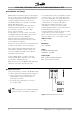
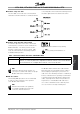
■ Network Connection
Connect the frequency converter to the Modbus RTU in
accordance with the following procedure (see Figure 1).
1. Connect signal wires to terminal 68 (P+) and
terminal 69 (N-) on main control board of
the frequency converter.
2. The shield of the cable must be connected
to the cable clamps.
NB!:
It is recommended to use shielded, twisted-pair
cables to reduce noise between conductors.
Figure 1 Network Terminal Connection
MG.10.S2.02 - VLT is a registered Danfoss trademark
8