
Operating instructions

VLT
®
2800, VLT
®
6000 HVAC and VLT
®
8000 AQUA Modbus RTU
Installation and
Setup
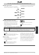
■ Hardware Setup VLT 2800
The VLT 2800 control card does not have build-in
termination network for RS 485. To terminate with the
correct impedance in the network the following resistors
shouldbeappliedatthefirstandthelaststation.
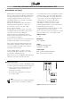
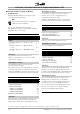
■ Hardware Setup VLT 6000 and VLT 8000
A terminator dip switch on the main control board
of the frequency converter is used to terminate the
Modbus RTU bus. The switch positions shown
in Figure 2 demonstrate the factory setting. Table
1 lists the switch functions and settings required
for Modbus RTU operation.
Figure 2 Terminator Switch Factory Setting
NB!:
Factory setting for DIP Switch is on.
Table 1 Terminator Switch Functions and Modbus RTU
Switch Setting
Switches 2 & 3 Used for terminating an RS-485 interface. On first and last devices in a multiple device
network, or on the only device in a single device network, switches 2 and 3 must be ON.
On all other devices in a multiple device network, 2 and 3 must be OFF.
NB!:
Terminator switch positions must be set
correctly in accordance with Table 1 for proper
Modbus RTU serial communication.
■ EMC Precautions
The following EMC precautions are recommended
in order to achieve interference-free operation
of the Modbus RTU network.
NB!:
Relevant national and local regulations,
for example regarding protective earth
connection, must be observed.
The Modbus RTU communication cable must be
kept away from motor and brake resistor cables to
avoid coupling of high frequency noise from one
cable to the other. Normally a distance of 200 mm (8
inches) is sufficient, but it is generally recommended
to keep the greatest possible distance between the
cables, especially where cables run in parallel over
long distances. If the Modbus RTU cable has to
cross a motor and brake resistor cable they must
cross each other at an angle of 90 degrees.
MG.10.S2.02 - VLT is a registered Danfoss trademark
9