
Specifications


Trip
A state entered in fault situations, e.g. if the frequency
converter is subject to an over-temperature or when the
frequency converter is protecting the motor, process or
mechanism. Restart is prevented until the cause of the
fault has disappeared and the trip state is cancelled by
activating reset or, in some cases, by being programmed
to reset automatically. Trip may not be used for personal
safety.
Trip locked
A state entered in fault situations when the frequency
converter is protecting itself and requiring physical
intervention, for example, if the frequency converter is
subject to a short circuit on the output. A locked trip can
only be cancelled by cutting off mains, removing the cause
of the fault, and reconnecting the frequency converter.
Restart is prevented until the trip state is cancelled by
activating reset or, in some cases, by being programmed
to reset automatically. Trip locked may not be used for
personal safety.
VT characteristics
Variable torque characteristics used for pumps and fans.
VVC
plus
If compared with standard voltage/frequency ratio control,
Voltage Vector Control (VVC
plus
) improves the dynamics
and the stability, both when the speed reference is
changed and in relation to the load torque.
1.7
Power Factor
The power factor is the relation between I
1
and I
RMS
.
Power
factor
=
3 ×
U
×
I
1 ×
COS
ϕ
3 ×
U
×
I
RMS
The power factor for 3-phase control:
=
I
1
×
cos
ϕ1
I
RMS
=
I
1
I
RMS
since
cos
ϕ1 = 1
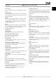
The power factor indicates to which extent the frequency
converter imposes a load on the mains supply.
The lower the power factor, the higher the I
RMS
for the
same kW performance.
I
RMS
=
I
1
2
+
I
5
2
+
I
7
2
+ . . +
I
n
2
In addition, a high power factor indicates that the different
harmonic currents are low.
The frequency converters built-in DC coils produce a high
power factor, which minimizes the imposed load on the
mains supply.
Introduction
VLT
®
HVAC Basic Drive FC 101 Design Guide
8 MG18C502 - Rev. 2013-09-06
1
1