
User's Manual

5
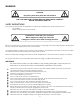
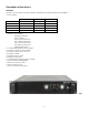
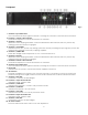
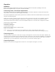
Frontpanel
Fig. 2
1. Channel 1 Input Attenuator.
Use to attenuate the input signal of channel 1. Pressing the control for 2 seconds mutes Channel 1.
2. Channel 1 volume scale indicator.
This indicator displays the volume attenuation of Channel 1.
3. Channel 1 clip LED.
Illuminates at the clipping threshold, Continuous illumination also indicates that ACL (Active Clip
Limiting) protection circuitry is engaged.
4. Channel 1/2 Limit LEDs.
Indicate that the ACL (Active Clip Limiting) protection circuitry is limiting the input signal to protect the
speakers from damage caused by a clipping amplifier.
5. Channel 1/2 TEMP LEDs.
These LEDs will light if the temperature of CH1 or CH2 exceeds 95
o
C.
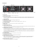
6. Channel 2 clip LED.
Illuminates at the clipping threshold, Continuous illumination also indicates that ACL (Active Clip
Limiting) protection circuitry is engaged,
7. Channel 2 volume scale indicator.
This indicator displays the volume attenuation of Channel 2.
8. Channel 2 Input Attenuator.
Use to attenuate the input signal of channel 2. Pressing the control for 2 seconds mutes Channel 2.
9. Power LED.
Indicates that AC power is connected and the amplifier is turned on.
10. Air entrance.
TAS Series amplifiers are cooled by two, rear-mounted fans, Cool air flows over the heat sinks and
exhausts through the rear grills, Make sure these outlets remain clear to allow unrestricted air flow.
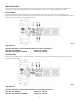
11. Channel 1 Mute LED.
If channel 1 is muted, the LED will light.
12. Channel 1 output level indicator.
Indication range: -22dB to +6dB.
13. Channel 1/2 VHF LEDs.
Indicates that channel 1 or 2 are in VHF protection mode.
14. Channel 1/2 ON LEDs.
Indicate that channel 1 or 2 are active.
15. Channel 1/2 DC LEDs.
Indicate that channel 1 or 2 are in protection mode.
16. Channel 2 output level indicator.
Indication range: -22dB to +6dB.
17. Channel 1 Mute LED.
If channel 2 is muted, the LED will light.
18. AC Power Switch.
This is the main Power switch. Press to turn the amplifier on.