
Installation & Assembly
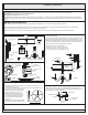

STEP 3 Install Canopy Chain Loop and Nipple
(Step 3 Continued)
-
* Pliers is required for this step.
A. Thread one Hex Nut (CC) to one end of the Nipple (DD) until it is at
least 0.25” from the end. Pass one Lock Washer (BB) over the end of
the Nipple (DD) and thread the Canopy Chain Loop (EE) onto the
Nipple (DD). By using pliers, thread the Hex Nut (CC) against the
Canopy Chain Loop (EE) and hand tighten until snug.
B. Thread another Hex Nut (CC) to the middle of the Nipple (DD). Place
another Lock Washer (BB) over the Nipple (DD) and then
thread the Nipple (DD) into the Crossbar (AA) until the Nipple (DD)
is about 0.375” above the Crossbar (AA).
C. Remove the Canopy Lock Ring (FF) from the Canopy Chain Loop
(EE). Place the Ceiling Canopy (HH) over the Canopy Chain Loop
AA
BB
CC
Step B
Step A
DD
CC
BB
EE
FF
Figure 3
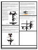
DD
Supply
Wires and
Ground Wire
EE
A
FF
GG
HH
Figure 4
STEP 4 - Install Fixture Chain and Ceiling Canopy
A. Pull the supply wires through the Canopy Lock Ring (FF) and the
Ceiling Canopy (HH) in order.
B. Connect the Small Loop (A) to Canopy Chain Loop (EE) by using the
Quick Link (GG). The fixture will hang safety now. Close the Quick
Link (GG).
C. Feed the Supply Wires and Ground Wire through the Canopy Chain
Loop (EE) and Nipple (DD) into the Outlet Box. Cut the wires leaving
approximately 8” of wire extending from the Outlet Box.
D. Refer to Step 5 for wire connections.
E. Raise the Ceiling Canopy (HH) and Canopy Lock Ring (FF) up the
Quick Link (GG) and over the Canopy Chain Loop (EE). Tighten the
Canopy Lock Ring (FF) onto the Canopy Chain Loop (EE) until tight.
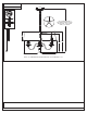
Figure 5
White wire
from supply
Ribbed side of wire from fixture
identified with the Label “N”
Black wire from
supply (or Red)
Smooth side of wire from fixture
identified with the label “L”
Ground wire
from supply
Ground wire
from fixture
HH
(EE) against the ceiling to
determine the correct
position of the Nipple
(DD). Thread the Canopy
Lock Ring onto the
Canopy Chain Loop (EE).
Adjust the Nipple (DD) to
allow the Ceiling Canopy
(HH) to rest against the
ceiling when held in place
by the Canopy Lock Ring
(FF).
D. Remove the Canopy Lock
Ring (FF) and the Ceiling
Canopy (HH). Tighten the
Hex Nut (CC) against the
Crossbar (AA) to secure
in place.
STEP 5 - Wire Connections
A. Use standard wire connectors (not included) to make all wire
connections. (Connectors are not included with fixture.) Twist
connectors until wires are tightly joined together. Wrap each
connection with approved electrical tape and carefully stuff all the
connected wires into outlet box.
Note: If the electrical wire is going to be cut shorter than provided
you will need to identify the "L" line wire and the "N" neutral wire
before you cut the excess wire off. One is labeled N and the other
labeled L. To do this separate the "L" line wire and the "N" neutral
wire as far as you need to. Re-label the wire near where you want to
make the cut. Be sure to mark the wire on the side of the fixture and
not on the excess wire being cut and removed.
STEP 6 - Install Crystal, Cap, Socket Cup, Cover and Bulbs
A. Pass Crystal (I), Cap (H) and Socket Cup (G) over Candle Covers in
turn as shown. Place Covers (F) onto top end of Candle Covers.
B. Insert bulbs and screw snugly into place.
Your fixture is now assembled and ready to use. Enjoy!
I
H
G
F
Bulb (not
supplied)
Candle
Cover
Figure 6
2of3