
Data Sheet
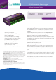

Technical Specifications
Analog Channels
16 analog input channels (expandable to 320*)
Each channel is independent and supports: one isolated 3-wire
or 4-wire input, or two isolated 2-wire inputs, or three common
referenced 2-wire inputs.
The following maximums apply.
• Two wire with common reference terminal: 48 (expandable to
960*)
• Two wire isolated: 32 (expandable to 640*)
• Three and four wire isolated: 16 (expandable to 320*)
*Expansion requires optional CEM20
Fundamental Input Ranges
The fundamental inputs that the DT85G can measure are voltage,
current, resistance and frequency. All other measurements are
derived from these.
Sampling
Integrates over 50/60Hz line period for accuracy
and noise rejection
Maximum sample speed: 40Hz
Effective resolution: 18 bits
Linearity: 0.01%
Common mode rejection: >90dB
Line series mode rejection: >35dB
Inputs
Inter-Channel Isolation: 100V (relay switching)
Analog Section Isolation: 100V (opto-isolated)
Input impedance: 160KΩ, >100MΩ
Common mode range: ±3.5V or ±55V (attenuator on/off)
Sensor Excitation (Supply)
Analog channels:
• selectable 2μA, 213μA or 2.5mA precision current source
• 4.5V voltage source
• switched external supply
General Purpose: Switchable 12V/5V regulated supply for powering
sensors & accessories (max 300mA).
Analog Output
Isolated programmable 16-bit DAC: voltage 0-10V or current
0-24mA
Analog Sensors
Supports a wide range of sensors including, but not limited to, those
listed below. A wide range of sensor scaling and linearising facilities
including polynomials, expressions and functions.
Thermocouples
Types: B, C, D, E, G, J, K, N, R, S, T
Calibration standard: ITS-90
RTDs
Materials supported: Pt, Ni, Cu
Resistance range: 10Ω to 1MΩ
Vibrating Wire
Frequency range: 500 to 5kHz
Coil resistance: 50 to 200Ω
Stimulation method: single pulse pluck
Thermistors
Types: YSI 400xx Series, other types*
Resistance range: up to1MΩ
* Other thermistor types are supported by thermistor scaling and
calculated channels.
Monolithic Temperature Sensors
Types supported: LM34 - 60, AD590, 592, TMPxx,
LM135, 235, 335
Strain Gauge and Bridge Sensors
Configurations: ¼, ½, & full bridge
Excitation: voltage or current
4-20mA Current Loop
Internal 100Ω shunt or external shunt resistor
Digital Channels
Digital Input/Outputs
8 bi-directional channels
Input Type: 8 logic level (max 20/30V)
Output Type: 4 with open drain FET(max: 30V, 100mA)
4 with logic output
Relay Output
1 latching relay, contacts (max: 30Vdc, 1A)
Counter Channels
Low Speed Counters
8 counters shared with digital inputs.
Low speed counters do not function in sleep mode.
Size: 32 bit Max Count rate: 10 Hz
Dedicated Counter Inputs
4 high speed or 2 phase encoder (quadrature) inputs
Size: 32 bit Max Count rate: 100 kHz
Input type:
• 2 logic level inputs (max ±30V),
• 2 sensitive inputs (100mV) for magnetic pickups (max ±10V)
Serial Channels
SDI-12
4 SDI-12 inputs, shared with digital channels. Each input
can support multiple SDI-12 sensors.
Generic Serial Sensor
Flexible options to allow data to be logged from a wide
range of smart sensors and data streams.
Available ports: Serial Sensor Port (RS232, RS422, RS485)
Host RS232 Port*
Baud rate: 300 to 115,200
*If used as a Serial Sensor channel then the Host Port is not available
for other communications.
Calculated Channels
Combine values from analog, digital and serial sensors
using expressions involving variables and functions.
Functions: An extensive range of Arithmetic,Trigonometric,
Relational, Logical and Statistical functions are available.
Alarms
Condition: high, low, within range and outside range
Delay: optional time period for alarm response
Actions: set digital outputs, transmit message, execute
any dataTaker command.
Scheduling of Data Acquisition
Number of schedules: 11
Schedule rates: 10ms to days
Data Storage
Internal Store
Capacity: 128MB (approx 10,000,000 data points)
Larger storage available refer to technical support.
Removable USB store device (optional accessory)
Types: compatible with USB 1.1 or USB 2.0 drives,
e.g. Flash drive.
Capacity: approx. 90,000 data points per megabyte.
Communication Interfaces
Ethernet Port
Interface: 10BaseT (10Mbps)
Protocol: TCP/IP, Modbus (Master & Slave)
USB Port
Interface: USB 1.1 (virtual COM port)
Protocol: ASCII command
Host RS232 Port
• Speed: 300 to 115,200 baud (57,600 default)
• Flow Control: Hardware (RTS/CTS), Software (XON/XOFF), None
• Handshake lines: DCD, DSR, DTR, RTS, CTS
• Modem support: auto-answer and dial out
• Protocols: ASCII Command, TCP/IP (PPP), Modbus (Master &
Slave), Serial Sensor
Serial Sensor Port
• Interface: RS232, RS422, RS485
• Speed: 300 to 57,600 Baud
• Flow Control: Hardware (RTS/CTS), Software (XON/XOFF), None
• Protocols: Modbus (Master & Slave), Serial Sensor
Network (TCP/IP) Services
Uses Ethernet and/or Host RS232 (PPP) ports
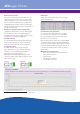
Command Interface
Access the ASCII command interface of the DT85G via TCP/IP
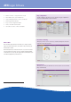
Web Server
Access current data and status from any web browser.
Custom pages can be defined. Download data in CSV
format. Command interface window. Define mimic displays.
Modbus Server (slave)
Access current data and status from any Modbus client
(e.g. SCADA system)
Modbus Client (master)
Read/write data from modbus sensors and devices
including PLC’s, dataTaker loggers, modbus displays etc.
FTP Server
Access logged data from any FTP client or web browser
FTP Client
Automatically upload logged data direct to an FTP server
System
Display and Keypad
Type: LCD, 2 line by 16 characters, backlight.
Display Functions: channel data, alarms, system status.
Keypad: 6 keys for scrolling and function execution.
Status LEDs: 4 for sample, disk, attention and power.
Firmware Upgrade
Via: RS232, Ethernet, USB or USB disk.
Real Time Clock
Normal resolution: 200 μs
Accuracy: ±1 min/year (0°C to 40°C),
±4 min/year (-40°C to 70°C)
Power Supply
External voltage range: 10 to 30Vdc
Peak Power: 12W (12Vdc 1A)
Average power Consumption
Using 12Vdc external power source
Physical and
Environment
Construction: Powder coated zinc and anodized aluminum.
Dimensions: 300 x 137 x 65mm
Weight: 2.5kg (5kg shipping)
Temperature range:–45°C to 70°C*
Humidity: 85% RH, non-condensing
*reduced battery life and LCD operation outside range –15°C to
50°C
Accessories Included
Resource CD: includes software, video training
and user manual.
Comms cable: USB cable
Line adaptor: 110/240Vac to 15Vdc, 800mA
For full technical specifications download the
user’s manual from our website.
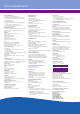
Sampling Speed Average Power
1 second 1350 mW
5 seconds 500 mW
30 seconds 135 mW
5 minutes 70 mW
1 hour 60 mW