Dayt i m e Fa n - A s pir ate d Radiation Shield Kit Installation Manual for Vantage Pro & Vantage Pro Plus Stations Introduction These instructions describe how to upgrade a non-aspirated Vantage Pro radiation shield to a Daytime Fan-Aspirated Radiation Shield. The upgrade kit can be installed on any Vantage Pro® or Vantage Pro Plus Integrated Sensor Suite (ISS) equipped with a round-plate non-aspirated, radiation shield.
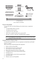
#8-32 x 1/2" Screws (3) #8-32 x 3-1/4" Screws (3) Threaded Spacers (3) Power Cable Assembly #8 Split-Lock Washers (6) Cable Tie Mount #8 Flat Washers (6) #4 x 3/8" Screw #4 Flat Washer Cable Clamp 4" Cable Tie 12" Cable Ties (2) Figure 2.
Installing the Daytime Fan Kit Put Console in Setup Mode 1. At your Vantage Pro console, press and hold the DONE key and then press the key to put the console in Setup Mode. This prevents the reception of erroneous data from the rain collector while you are removing the ISS. Note: If the console acquires erroneous data during the upgrade, refer to “Take the Console Out of Setup Mode” on page 14 for instructions on clearing data.
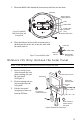
Disassemble the Standard Radiation Shield Note: We recommend using a workbench or table to perform the following procedures. 1. 2. 3. 4. 5. Turn the ISS upside down with the rain collector cone on the bottom. Disconnect the RAIN cable and, if present, disconnect the SUN and UV cables from the SIM. Wireless ISS Only: Disconnect the solar power cable. Turn the ISS right-side up with the cone on top. Remove the rain collector cone from the ISS base by rotating the cone counter-clockwise.
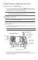
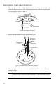
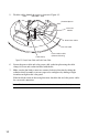
7. Route the RAIN cable behind the drain and out the hole near the drain. ISS Base Rain Collector Tipping Bucket Drain RAIN Cable Install Cable Tie Mount Here Route Cable Here Figure 6. Route RAIN Cable Around Drain and through Hole 8. Place the adhesive-backed cable tie mount next to the hole near the drain, and secure the cable with the small cable tie. Cable Tie RAIN Cable Figure 7.
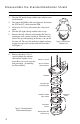
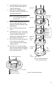
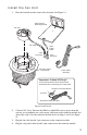
Assemble the Lower Section 1. The top plate in the ISS radiation shield has a thick, insulating disk attached on the underside. Remove the two screws holding the insulating disk and discard the disk. Save the top plate for use in Step 3. Top Plate Insulating Disk Figure 9. Remove the Insulating Disk 2. Remove the Temp/Hum sensor from the bottom plate. Screws (3) Flat Washer Temp/Humidity Sensor Cable Clamp Cable Clamp Mounting Hole Figure 10. Temp/Hum Sensor Removal and Installation 3.
4. 5. Start building the lower section of the new radiation shield with the original bottom plate. Place the new Temp/Hum plate from Step 3 and two open plates on top of the bottom plate. Note: When stacking plates, make sure the screw bosses (holes) line up with each other. Open Plate TEMP HUM Sensor Cable Open Plate 6. Run the TEMP HUM cable over the top of second open plate directly above the cable port openings in the SIM housing. 7. Place the third open plate on the stack. 8.
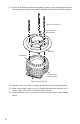
11. Lower the Fan Plate onto the stack making sure the screw goes through the boss in each of the plates and lines up with the threaded insert located in the bottom plate. #8-32 x 4" Screws (3) #8 Lock Washer #8 Flat Washer Fan Plate Screw Boss Threaded Insert in Bottom Plate Figure 13. Install Fan Plate 12. Turn the screw a few times to engage the threaded insert in the bottom plate. 13.
Install the Fan Unit 1. Place the fan unit into the center of the fan plate. See Figure 14. Solar Panel & Mounting Bracket Fan Unit Fan Cable Solar Power Cable 3-Pin Connector 2-Pin Connector Put Power Cable Clamp Here Power Cable Assembly Important - Cabled ISS Only!! Cut Connector Module off the Power Cable Assembly before connecting fan or solar panel. Keep the Connector Module Cut Here Discard the rest of the cable Figure 14. Install Fan Unit 2. 3. 4.
5. Tuck the cables behind the spacer as shown in Figure 15.. Threaded Spacer Connector Module Solar Power Cable Fan Unit Cable Cable Clamp Power Cable to SIM (Wireless ISS Only) Figure 15. Clamp Power Cable and Solar Power Cable 6. 7. Secure the power cable and solar power cable to the fan plate using the cable clamp, #4 screw and washer included with the kit.
Assemble the Upper Section 1. 2. Place the open cap plate (has hole in center) on top of the fan plate, then place the closed cap plate (no hole). See Figure 18. ‘ Upper Shield Assembly” on page 12. Place the solar panel bracket on top of the stack with the panel located near the hinge side of the SIM housing. Line up the screw bosses in the radiation shield stack with the solar panel mounting bracket holes. See Figure 16. Solar Panel Mounting Bracket Radiation Shield Mounting Holes (3) Figure 16.
Insert this screw first #8-32 x 3-1/4" Screws (3) 5. 6. 7. Lower the ISS base onto the stack so that the screw goes into the boss nearest the solar panel.Turn the screw a few times to engage the threads. Place a lock washer and washer on the other two 3 1/4” screws then insert them through the remaining two screw holes. Tighten all three screws to securely fasten the radiation shield and solar panel bracket to the ISS base.
Re-Install the ISS 1. Install the rain collector cone and turn the ISS upside down. Open the SIM cover and connect the TEMP/HUM and RAIN sensor cables. If installed on your station, connect cable for the UV and SUN sensors. 2. 3. Cable Routing Channels (press cables fully into channel) Optional 3-Volt Lithium Battery (Wireless ISS Only) UV SUN RAIN WIND Power Cable (Wireless ISS Only) AC Power (optional) Console Cable (Cabled ISS Only) TEMP HUM DIP Switches (Wireless ISS Only) Figure 19.
Take the Console Out of Setup Mode 1. 2. At your Vantage Pro console, press the DONE key to take the console out of Setup Mode. Check the console for erroneous rain data and clear if necessary. To clear erroneous data: a. Select the weather variable to be cleared. b. Press and release the 2ND key, then immediately press and hold the CLEAR key. The daily rain reading will start blinking. c. Keep holding CLEAR until the reading changes to zero. d.
Troubleshooting If you are experiencing problems performing the upgrade or have problems with your Daytime Fan-Aspirated Radiation Shield, first be sure to check all cable connections. If you are unable to solve the problem, please call Davis Technical Support. We’ll be glad to help. Most questions can be answered over the phone. You can also email us for support or visit our website. Sorry, we are unable to accept collect calls.
© Davis Instruments Corp. 2003-2004. All rights reserved. Daytime Fan-Aspirated Radiation Shield Kit Installation Manual Rev B, January 16, 2004 Document: 07395.033 Product: 7745 Vantage Pro is a registered trademark of Davis Instruments Corp. This product is protected in the United States by Patent Number 6,247,360. 3465 Diablo Avenue, Hayward, CA 94545-2778 U.S.A. 510-732-9229 • Fax: 510-732-9188 E-mail: info@davisnet.com • www.davisnet.