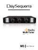
Multi-Tuner Monitor M3 User Manual
Welcome" Thanks for purchasing the DaySequerra M3 HD RadioTM Multi-Tuner. We design and build all of our DaySequerra products to be completely reliable and easy to use, so you can concentrate on producing great sounding broadcasts, not struggling with complicated equipment or difficult to use product manuals.
Table"of"Contents" Important Safety Information 4 Service Information 4 Introduction 4 M3 Key Features 5 M3 Technical Specifications 5 Unpacking and Installing 6 Front Panel Controls and Indicators 6 Rear Panel Controls and Connectors 9 M3 Operating Description 10 Sample VFD Displays 12 Performance Loss Monitor 18 User Settings 23 One Year Warranty 24 " " " All rights reserved DaySequerra Corp, Copyright 2011.
Important"Safety"Information" • • • • • • • • • • Indoor use only. Not for use in wet or damp environments. Maximum Relative Humidity: <80% Class I Equipment (grounded type) Electrical rating: 100-120/220-240V~50-60Hz 18W Fuse Rating: 2A 250V 20MM AC Mains supply voltage fluctuations are not to exceed +10% of the nominal voltage Operations temperature range -40°C to 70°C Maximum altitude: 3000m (9843ft) Equipment suitable for continuous operation Weight: 8.2kg (18lbs) equipment only; 10.
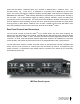
M3"Key"Features THREE SEPARATE AM, FM AND HD RADIO™ TUNERS - dedicated vacuum florescent displays SEPARATE AM AND FM ANTENNA INPUTS – Industry standard 75-ohm “F” connectors DEDICATED HD LOCKED, MULTICAST AVAILABLE, DELAY SET AND TUNER ALARM STEREO ANALOG OUTPUTS – Balanced (+4dBm) for 100% analog modulation AES3 DIGITAL AUDIO OUTPUTS – full-time for all broadcast audio; 110-ohm transformer isolated IEC320 POWER INLET – 120/240VAC via internal solder jumpers; integrated fuse holder SYNTHESIZED, PUSHBUTTON T
Unpacking"and"Installing"the"M3 Immediately upon receiving your M3, please make a careful inspection for any shipping damage. If damage is found or suspected, please notify the carrier at once and then contact your dealer.! ! The DaySequerra M3 is shipped in one carton, which contains: the M3 unit, an AC power cable and this User Manual. We strongly encourage you to save the shipping carton and shipping materials supplied with your M3.
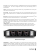
UP and DN – For manual AM and FM tuning in TUNER BAND mode and scrolling through PRESETS in PRESETS mode. Also used to navigate Mode Service, Forcing and Data Display menus, as described below. SELECT – Multi-function switch for selecting multicast tuning, storing PRESETS and controlling other tuner functions, as described herein.
Shared Controls and Displays The following controls and displays are ‘shared’ among the three tuner module based on the Tuner 1, 2, 3 switch selection. TUNER 1, 2, 3 – Selects the tuner module to receive front panel switch activity via the system processor and bus. ALARM SETUP - A momentary push of this switch enables the alarm setup menu in the selected tuner module’s VFD. Hold this switch for 5 seconds to arm the alarms as configured in the alarm setup menu.
Press and hold DATA - DISPLAY switch for 5 seconds to activate DATA - DISPLAY menu. The firmware version, e.g., “v4.0.9 A3.2.1” is displayed for 5 seconds before displaying the first menu option. The menu’s first selection enables or disables “Scrolling Data” mode where tuner displays each RDS/RBDS and HD RadioTM PSD message data field for approximately 5 seconds before scrolling to the next field.
M3 Operating Description Power-up and Standby. The power switch is located on the rear panel of the M3; when switched on, the tuner displays the hardware and software version of the M3 to be displayed for 3 seconds on Tuner 1’s VFD. If rear panel AC switch is turned off or if the power is momentarily interrupted, all tuner modules and M3 control/status returns to its previous state. Front Panel Locked.
SELECT Control. When tuned to an HD RadioTM HD-1 signal and at least one multicast broadcast is present, i.e., HD-2 through HD-8, momentarily depressing the SELECT switch puts tuner into multicast tuning mode, and automatically tunes the tuner module to the first multicast broadcast available. Use the UP control to scroll through all of the multicast stations available. Use the DN control to exit multicast tuning mode and re-tune to the HD-1 signal.
The MODE – SERVICE menu options are MODE, SERVICE and DIAGNOSTICS outlined as follows: M O D E < • M S O E D R E V I C E > Selecting MODE activates the MODE option to display the HD RadioTM broadcast’s Service Mode and MPA Codec Mode. Service Mode - Displays the current Service Mode being broadcast. Valid Service Modes are MP1 or MP5 or MP6 for FM and MA1 or MA3 for AM. MPA Codec Mode - Displays the MPA Codec mode if digital audio was acquired. Valid MPA Codec Mode values are 0-3.
• Selecting DIAGNOSTICS activates the DIAGNOSTICS option to display the HD RadioTM broadcast parameters described below as well as initiate collection of bit-error rate and blockerror rate when a BER-BLER test vector is being broadcast. M < • O D D I E A G S N E O R S V T I I C C E S > Carrier-to-noise ratio and signal-to-interference ratio values are displayed on first DIAGNOSTICS screen.
• When the HD RadioTM broadcast exciter is put into Bit Error Rate Mode and a special test vector is being broadcast, the Channel Error window displays bit error rate information for P1, P2, P3 logical channels and block error rate information on the PIDS logical channel. Sample BER-BLER VFD Display B I T E B L O C K • I L T O O R R R O 3 7 R E E - 5 8 C E K R R E O R R R O N N R A A Next momentary push of UP, DN or SELECT scrolls to root MODE – SERVICE menu.
The first press of the FORCING switch when tuned to an HD-1 displays the A-D SPLIT Forcing menu. Exit the FORCING mode or FORCING menu at any time by pressing FORCING switch. F < O R A C D I N S G P L M I E T N U > Use the UP or DOWN switches to change the selection and press SELECT to set the Forcing mode. If SELECT is pressed when AD SPLIT is selected, the A-D Split mode is enabled and the display changes to the following: Sample A-D Split VFD Display F M 1 A D S P 0 L 8 I .
DATA - DISPLAY Menu – Press the DATA - DISPLAY switch in for 5 seconds to activate the DATA DISPLAY menu. The firmware version, e.g., “V3.2.0 A3.5.0” is displayed for 5 seconds before displaying the first menu option. Blue arrow LED illuminates only when switch is being pushed, or when DATA - DISPLAY menu is active. Exit the DATA - DISPLAY menu at any time by pressing DATA DISPLAY switch.
• • • • • • Album Genre URL ID Comment Commercial Sample PAD Song Title Field Display F M 9 5 W H Y C A N . ‘ 7 T T H H D I S 1 B Subsequent momentary push of DATA - DISPLAY switch turns DATA - DISPLAY mode and DATA DISPLAY LED off. VFD display second line scrolls if PAD field is longer than 16 characters. If there is no data for the selected field, VFD displays “NO” plus the data category, e.g., “NO ALBUM DATA.
Performance Loss Monitor Performance Loss Monitor (PLM) Connections – The PLM provides Normally Open opto-isolated alarm outputs on a rear panel mounted DB15 connector to report selected alarm conditions, including loss of RF carrier, program audio, OFDM lock and PAD data on each Tuner Module. The following lists the DB15 pin-outs. Relay contacts are rated at 10mA @ 24VDC.
Alarm Output 1 – RF Carrier Loss (alarm based on analog RF signal strength) • R F > S • R Highlight desired “SET” or “OFF” option using UP and DN switches to toggle the setting. Select “SET” to set this tuner alarm and continue with alarm configuration menu; select “OFF” to set this tuner alarm function to off. Push “SELECT” to continue. F L R < R I E R L O O F S F S C W A R > R M I E E D R < L H E I V G E H L Push “SELECT” switch to increment the menu to the next alarm function.
• If “SET” is selected, submenu for “Level” threshold with “LOW”, “MED” and “HIGH” options is displayed next. “LOW” option sets audio loss threshold for approximately -60dB; “MED” option sets audio loss threshold for approximately -40dB; and “HIGH” option sets audio loss threshold for approximately -20dB. Use UP and DN switches to toggle the setting and highlight the desired option. Push “SELECT” switch to continue.
Alarm Output 4 – RBDS Data Loss alarm based on data present (not valid) in Radio Text field. R > B S • S T D A T A L O < O F S F S If “SET” is selected, submenu for “Alarm Delay” with “30”, “60”, “120” and “240” second options is displayed next. Use UP and DN switches to toggle the setting and highlight the desired option. A 0 3 D E L > A 6 R 0 M < 1 2 D 0 E L 2 A 4 Y 0 S Push “SELECT” switch to save and increment the menu to the next alarm function.
• > A M Highlight desired MC Available - “MC-AV”, Delay Bit – “DLAY” or “OFF” option using UP and DN switches to toggle the setting. Select desired function to be alarmed and continue with alarm configuration menu; select “OFF” to set this tuner alarm function to off. Push “SELECT” to continue. L C • R A M V < O D U L T A P Y U T O F 6 F If “MC-AV” or “DLAY” is selected, submenu for “Alarm Delay” with “30”, “60”, “120” and “240” second options is displayed next.
Front panel of the tuner is locked whenever alarm is armed to prevent false alarm conditions. De-activate Alarm - To de-activate the configured alarm functions, press the CLEAR ALARMS button for 5 seconds. Tuner VFD display returns to normal operation and front panel of the tuner is unlocked.
DaySequerra – One Year Limited Warranty DaySequerra warrants this product to be free from defects in materials and workmanship to its original owner for one (1) year from the date of purchase. DaySequerra will repair or replace such product or part thereof that upon inspection by DaySequerra, is found to be defective in materials or workmanship subject to conditions contained herein. DaySequerra products are sold worldwide, through a network of authorized DaySequerra dealers and distributors.