
User manual

8"
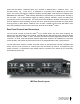
M3#User#Manual#
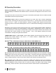
Shared Controls and Displays
The following controls and displays are ‘shared’ among the three tuner module based on the Tuner 1,
2, 3 switch selection.
TUNER 1, 2, 3 – Selects the tuner module to receive front panel switch activity via the system
processor and bus.
ALARM SETUP - A momentary push of this switch enables the alarm setup menu in the selected tuner
module’s VFD. Hold this switch for 5 seconds to arm the alarms as configured in the alarm setup
menu.
CLEAR ALARMS - A momentary push of this switch clears all active alarms for the selected tuner
module. The Alarm LED then goes back to solid, the beeper stops and the rear panel contact opens.
Hold this switch for 5 seconds to disarm the alarms as configured in the alarm setup menu.
TUNER BAND – Selects manual AM and FM tuning for the selected tuner module; tune using the
dedicated UP and DN controls. Blue arrow LED illuminates when mode is active.
PRESETS – Each tuner module has capability to recall 20 stored AM stations and 20 stored FM
stations – for a total of 120 stations. PRESETS control selects PRESETS mode for the selected tuner
module; scroll through stored stations using the dedicated UP and DN controls. Blue arrow LED
illuminates when tuner is in PRESETS mode. When in PRESETS mode, second momentary push of
PRESETS switch toggles between AM and FM stored presets.
MODE - SERVICE – Momentary push activates MODE – SERVICE menu. Blue arrow LED illuminates
only when switch is being pushed, or when MODE – SERVICE menu is active. In any active mode,
second momentary push of MODE – SERVICE at any time clears mode. The MODE – SERVICE menu
options are MODE, SERVICE and DIAGNOSTICS.
FORCING – The FORCING control is used to setup the forcing state of the selected tuner module.
Blue arrow LED illuminates only when switch is being pushed, or when FORCING menu is active. The
FORCING menu contains three options: Forced Analog, Forced Digital and A-D Split; options are
dependent on the type of broadcast being received, i.e., HD-1, multicast HD-2 through HD-8, or analog,
as described below. In any active mode, second momentary push of FORCING control at any time
clears mode.
DATA - DISPLAY and DATA - DISPLAY Menu – Selects decoded RDS/RBDS from an analog FM
broadcast and PSD messages from an HD Radio
TM
broadcast for display on the second line of the
VFD. Momentary push DATA - DISPLAY switch scrolls display through each RDS/RBDS and HD
Radio
TM
PSD message data field, as described below.