
User manual

M3#User#Manual#
9"
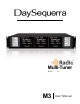
Press and hold DATA - DISPLAY switch for 5 seconds to activate DATA - DISPLAY menu. The
firmware version, e.g., “v4.0.9 A3.2.1” is displayed for 5 seconds before displaying the first menu
option. The menu’s first selection enables or disables “Scrolling Data” mode where tuner displays each
RDS/RBDS and HD Radio
TM
PSD message data field for approximately 5 seconds before scrolling to
the next field. UP or DN switches toggle the setting; pressing “SELECT” saves the setting and
increments the menu to the next field. The second menu field enables or disables “Audio Muting.” Next
press of “SELECT” saves the setting and exits the menu. Blue arrow LED illuminates only when switch
is being pushed, or when DATA - DISPLAY menu is active. Default is AUTO mode with station short
name to be displayed in second line of VFD when tuned to an HD Radio
TM
station.
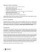
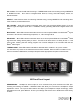
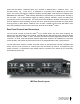
Rear Panel Controls and Connectors
The rear panel consists of three HD Radio
TM
tuner module areas, with each area containing the
following for each HD Radio™ tuner module: separate AM and FM antenna inputs, balanced analog
stereo audio outputs at +4dBV on XLR connectors, transformer-isolated digital audio output on XLR
connector—44.1kHz, 16-bit that provides full-time digital audio output for all broadcasts (5.1 surround
sound capable), and a DB15 connector with access to six assignable alarm relay contact closures.
The rear panel also contains a master AC power switch, an IEC320 power inlet with integrated fuse
holder, and an RJ-45 connector or ‘network port’ that will initially be used for re-programming the
system processor. A 120/240VAC input voltage selector is located on the bottom of the unit directly
underneath the power inlet.
M3 Rear Panel Layout