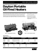
2E510E, 2E511E, 3E218E, and 3E219D Operating Instructions & Parts Manual Please read and save these instructions. Read carefully before attempting to assemble, install, operate or maintain the product described. Protect yourself and others by observing all safety information. Failure to comply with instructions could result in personal injury and/or property damage! Retain instructions for future reference.
E510E, 2E511E, 3E218E, and 3E219D Dayton Operating Instructions and Parts Manual Dayton Portable Oil-Fired Heaters ® Specifications (Continued) ELECTRICAL SPECIFICATIONS Model Electrical Input Amperage (during normal run) 2E510E 2E511E 3E218E 3E219D 120 Volt/60 Hertz 120 Volt/60 Hertz 120 Volt/60 Hertz 120 Volt/60 Hertz 2.0 2.0 3.6 3.
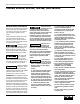
Dayton Operating Instructions and Parts Manual Models 2E510E, 2E511E, 3E218E, and 3E219D General Safety Information Make certain you read and understand all warnings. Keep these instructions for reference. They are your guide to safe and proper operation of this heater. Safety information appears throughout these instructions. Pay close attention to them. Below are definitions for the safety information listed throughout this manual.
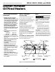
2E510E, 2E511E, 3E218E, and 3E219D Dayton Operating Instructions and Parts Manual Dayton Portable Oil-Fired Heaters ® General Safety Information (Continued) Theory of Operation Fuels THE FUEL SYSTEM • Heaters used in the vicinity of tarpaulins, canvas, or similar enclosure materials shall be located a safe distance from such materials. The recommended minimum safe distance is 10 feet. It is further recommended that these enclosure materials be of a fire retardant nature.
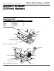
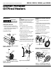
Dayton Operating Instructions and Parts Manual Models 2E510E, 2E511E, 3E218E, and 3E219D Assembly (For Models 3E218E and 3E219D Only) These models are furnished with wheels and handles. Wheels, handles, and the mounting hardware are found in the shipping carton. TOOLS NEEDED • MEDIUM PHILLIPS SCREWDRIVER • 3/8" Open or Adjustable Wrench • Hammer 1. Slide axle through wheel support frame. Install wheels on axle.
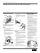
2E510E, 2E511E, 3E218E, and 3E219D Dayton Operating Instructions and Parts Manual Dayton Portable Oil-Fired Heaters ® Maintenance FAN Never service heater while it is plugged in, operating, or hot. Severe burns and electrical shock can occur. UPPER SHELL REMOVAL 1. Remove screws along each side of heater using 5/16" nut-driver. These screws attach upper and lower shells together (See Figures 7 and 8). IMPORTANT: Remove fan from motor shaft before removing motor from heater.
Dayton Operating Instructions and Parts Manual Models 2E510E, 2E511E, 3E218E, and 3E219D Fuel Filter Maintenance (Continued) PUMP PRESSURE ADJUSTMENT 1. Remove pressure gauge plug from filter end cover (See Figure 12). Pressure Gauge 2. Install accessory pressure gauge (Part Number HA1180) (See Figure 13). 3. Start heater (See Operation, page 5). Allow motor to reach full speed. 4. Adjust pressure. Turn relief valve to right to increase pressure. Turn relief valve to left to decrease pressure.
2E510E, 2E511E, 3E218E, and 3E219D Dayton Operating Instructions and Parts Manual Dayton Portable Oil-Fired Heaters ® Maintenance (Continued) IGNITOR 1. Remove upper shell and fan guard (See page 6). 2. Remove fan (See page 6). 6. Remove combustion chamber. Stand combustion chamber on end with nozzle adapter bracket on top (See Figure 17). Ignitor Screw/Washer Assembly Ignitor 3. Remove 4 side cover screws with a 5/16" nut driver. Remove side cover (See Figures 14 and 15). 4.
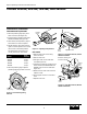
Dayton Operating Instructions and Parts Manual Models 2E510E, 2E511E, 3E218E, and 3E219D Maintenance (Continued) Combustion Chamber 6. Carefully remove nozzle from the nozzle adapter using 5/8" socket wrench. Burner Strap Photocell Bracket Air Line Hose 5. Place plastic hex-body into vise and lightly tighten. Nozzle Face Nozzle/ Adapter Assembly Nozzle Sleeve Fuel Line Hose Nozzle Figure 20 - Removing Air and Fuel Line Hoses (150,000 Btu/Hr Model Only) Nozzle Adapter NOZZLE 1.
2E510E, 2E511E, 3E218E, and 3E219D Dayton Operating Instructions and Parts Manual Dayton Portable Oil-Fired Heaters ® Maintenance (Continued) PUMP ROTOR (Procedure if rotor is binding) 1. Remove upper shell (See page 6). 2. Remove filter end cover screws using 5/16" nut-driver (See Figures 24 and 25). 3. Remove filter end cover and air filters. 5. Remove pump plate. 15. Reinstall insert and rotor. 6. Remove rotor, insert, and blades. 16. Perform previous steps 10 through 12. 7.
Dayton Operating Instructions and Parts Manual Models 2E510E, 2E511E, 3E218E, and 3E219D Storing Transporting, or Shipping NOTE: If shipping, transport companies require fuel tanks to be empty. 1. Drain fuel tank. NOTE: Some models have drain plug on underside of fuel tank. If so, remove drain plug to drain all fuel. If heater does not have drain plug, drain fuel through fuel cap opening. Be sure all fuel is removed. 2. Replace drain plug if provided. 3.
2E510E, 2E511E, 3E218E, and 3E219D Dayton Operating Instructions and Parts Manual Dayton Portable Oil-Fired Heaters For Replacement ®Parts, Call 1-800-323-0620 24 Hours A Day - 365 Days A Year 1 Please provide following information: -Model number -Serial number (if any) -Part description and number as shown in parts list 2 3 Address parts correspondence to: Grainger Parts Operations P.O. Box 3074 1657 Shermer Road Northbrook, IL 60065-3074 U.S.A.
Dayton Operating Instructions and Parts Manual Models 2E510E, and 3E219D Models 2E510E, 2E511E, 2E511E, 3E218E, and 3E218E, 3E219D Replacement Parts List for Motor and Pump Assembly for Models 2E510E and 2E511E - Figure 29 Ref. No. 1 2 Description Part Number Motor 102001-01 Pump Body 2E510E 2E511E Qty. Qty. 1 Ref. Ref. No. No. Description Part Number 2E510E 2E511E Qty. Qty.
2E510E and 3E219D 2E511E 2E510E, 2E511E, 3E218E, Dayton Operating Instructions and Parts Manual Dayton Portable Oil-Fired Heaters For Replacement ®Parts, Call 1-800-323-0620 24 Hours A Day - 365 Days a Year Please provide following information: -Model number -Serial number (if any) -Part description and number as shown in parts list 4 1 Address parts correspondence to: Grainger Parts Operations P.O. Box 3074 1657 Shermer Road Northbrook, IL 60065-3074 U.S.A.
Dayton Operating Instructions and Parts Manual Models 2E510E, 2E511E, and 3E219D Models 2E510E and 2E511E Portable 3E218E, Oil-Fired Heaters Replacement Parts List for Models 2E510E and 2E511E Ref. No. Part Number Description 2E510E 2E511E Qty. Qty. Ref. No. Description Part Number 2E510E 2E511E Qty. Qty.
3E218E 2E510E, 2E511E, 3E218E, and 3E219D Dayton Operating Instructions and Parts Manual Dayton Portable Oil-Fired Heaters For Replacement ®Parts, Call 1-800-323-0620 24 Hours A Day - 365 Days a Year Please provide following information: -Model number -Serial number (if any) -Part description and number as shown in parts list 2 Address parts correspondence to: Grainger Parts Operations P.O. Box 3074 1657 Shermer Road Northbrook, IL 60065-3074 U.S.A.
Dayton Operating Instructions and Parts Manual Models 2E510E, 2E511E, 3E218E, and 3E219D Model 3E218E Replacement Parts List for Model 3E218E Ref. No. Description Part Number Ref. Ref. No. No. Qty. Description Description Part Part 2E510E 2E511E Number Qty. Number Qty. Qty.
2E510E, 2E511E, 3E218E, and 3E219D Dayton Operating Instructions and Parts Manual Dayton Portable Oil-Fired Heaters For Replacement ®Parts, Call 1-800-323-0620 24 Hours A Day - 365 Days a Year Please provide following information: -Model number -Serial number (if any) -Part description and number as shown in parts list 2 Address parts correspondence to: Grainger Parts Operations P.O. Box 3074 1657 Shermer Road Northbrook, IL 60065-3074 U.S.A.
Dayton Operating Instructions and Parts Manual Models 2E510E, 2E511E, 3E218E, and 3E219D Model 3E219D Replacement Parts List for Model 3E219D Ref. No. Description 1 Upper Shell 2 #10-16 x 1/2" Screw 3 Part Number 098511-164 Qty. Ref. No. Description Part Number Qty.
2E510E, 2E511E, 3E218E, and 3E219D Dayton Operating Instructions and Parts Manual Dayton Portable Oil-Fired Heaters ® Replacement Parts List for Handle and Wheel Group Models 3E218E and 3E219D 1 Ref. No.
Dayton Operating Instructions and Parts Manual Models 2E510E, 2E511E, 3E218E, and 3E219D Wiring Diagram Ignitor (3E218E and 3E219D Models) Yellow (2E510E and 2E511E Models) Gray Yellow (3E218E and 3E219D Models) Gray (2E510E and 2E511E Models) Ignitor Thermostat Red Motor Main Black Black 120V (L1) Green Power Plug 120V/60Hz AC Neutral (L2) Motor Green Ignition Control White White Motor Return Ignitor Blue Photocell Photocell Blue Photocell Figure 36 - Wiring Diagram for All Models ® 10444
2E510E, 2E511E, 3E218E, and 3E219D Dayton Operating Instructions and Parts Manual Dayton Portable Oil-Fired Heaters ® Troubleshooting Chart Never service heater while it is plugged in, operating, or hot. Severe burns and electrical shock can occur. Symptom Possible Cause(s) Corrective Action Motor does not start five seconds after heater is plugged in 1. No power to heater 1. Check circuit breaker in electrical panel 2. Thermostat setting too low 2.
Dayton Operating Instructions and Parts Manual Models 2E510E, 2E511E, 3E218E, and 3E219D Troubleshooting Chart (Continued) Symptom Possible Cause(s) Corrective Action Heater ignites but ignition control assembly shuts heater off after a short period of time 1. Pump pressure incorrect 1. See Pump Pressure Adjustment, page 7 2. Dirty air intake, air output, and/or lint filter 2. See Air Output, Air Intake, and Lint Filters, page 6 3. Dirty fuel filter 3. See Fuel Filter, page 7 4.
2E510E, 2E511E, 3E218E, and 3E219D Dayton Operating Instructions and Parts Manual Dayton Portable Oil-Fired Heaters ® LIMITED WARRANTY DAYTON ONE-YEAR LIMITED WARRANTY. Portable Oil-Fired heaters, Models covered in this manual, are warranted by Dayton Electric Mfg. Co. (Dayton) to the original user against defects in workmanship or materials under normal use for one year after date of purchase.