
Manual

PAGE 2 - 6' Grasp Stair Rail_ENG
Installation Instructions continued
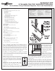
Step 5: Note! To ensure the balusters are installed plumb, the holes
between the rail sections must all be aligned. Tip: Use a gauge pin
or a 3/32" drill bit to ensure the holes are aligned.Usingthetrimmed
lowerrailasaguide,settheupperinnerrailforthesystemontopof
thetrimmedbottomrailandalignthepre-drilledholes.Markthecut
linesontheinnerrailwithapencil.Note! To allow for the thickness
of the brackets, the inner rails should be 1/8" shorter than the lower
rails with all holes equally spaced. Removeanadditional1/16"from
thepencilmarkoneachendandtrimtheinnerrailtolength.Repeat
forthesecondinnerrail(g.3).
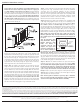
Step 6: Assemblethelowerinnerrailandsupportblockassembly.
Position the bottom rail between the posts. Check building code
requirementsformaximumspacingonastaircase,typicallylessthan
6".A6"ballcannotpassthroughthetriangleformedbythebottom
rail,treadandriser(g.4).Asupportblockisneededevery2'on-
center.Trimsupportblockstodesiredheightandpre-drill1/8"holes
intheproperlocation.Holesmustbecenteredontheinnerrailfor
support blockstotproperly.Usingthesupportblockconnectors,
fastensupportblockstotheundersideoftheinnerrail.
Step 7:Marktheheightofthebracketsontheinsideofthepost
usingthe bracket placementtemplate included inthekit. Another
optionistousetheinnerrailasaguide.Thetopofthebracketshould
beevenwiththetopoftheinnerrailassembly.Drilltwo1/8"holes
throughthebracketholesshownonthetemplateandthroughthepost
sleeve,forboththeupperandlowerbrackets.Removethebracket
placementtemplatefromthepostsleeveandfastentheupperand
lowerbracketstothepostusingtwo2"longcountersunkscrews.Tip:
For best results, use a long drill bit or add an extension bit to the drill.
Repeatontheadjacentpost.Settheinnerrailinplaceandpre-drill
eight1/8"holesateachbracketholeandintotheinnerrail.Fasten
therailtothebracketusingeight1"longcountersunkscrews.
Step 8: Setthelowerrailonthelowerinnerrailbetweentheposts.
Using two 2-1/2" long countersunk screws, set the two outermost
connectors. For co-ex composite balusters, use the connectors
thatcomewiththebalusterkit.ForDeckoratorsaluminumorglass
balusters, use the appropriate stair adaptor (sold separately) with
the proper baluster connector (sold separately). Using the screws
provided with the baluster connectors, install the balance of the
balusterconnectorsontothelowerrailassembly.
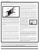
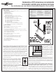
Step 9:Determinethelengthofthebalusters.Fig.3illustrateshow
a36"highrailingmightbe sized.Use g.3as a planningtool to
determinetheheighttocutthepostsleevesandthebalusters.Note:
Use a fixture to ensure a consistent length (+/- 1/16"). Ifusingco-
excompositebalusters,thebalusterwillneedtobemitercuttothe
proper stairangle.Trimthe balusters to the required angle (co-ex
composite balusters only)and length.(One per holeinlower rail).
Installbalustersoneachconnector.Gentlytapthebalusterswitha
rubbermallettoeliminateanygaps.Checkforlevelendtoend.Tip:
Wrap painters tape around the back side of both posts and place
balusters against the tape. The tape will balance the balusters in
place until the upper rails are installed. Remove tape when upper rail
is in place.
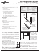
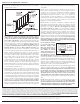
Step 10: Important: when
using Deckorators Designer
Baluster Connectors (both
Estate and Classic) in
conjunction with the stair
adaptors, the upper inner
rail must be inverted (fig. 5).
Use an exterior adhesive on
the underside of the Designer Baluster Connectors to prevent the
balusters from spinning. Install the remaining baluster connectors
andstairadaptors(ifapplicable)ontheundersideoftheupperinner
rail.Settherailontothebalusters,gentlytappingtherailtoremove
anygaps.Attachtheinnerrailtothebracketsbypre-drillingeight
1/8"holesateachbracketholeandintotheinnerrail.Fastentherail
tothebracketusingeight1"countersunkscrews.
Step 11:Measurethedistancebetweenthepostsandtrimthe
graspableupperouterrailtolength,andsetontheassembly.Taking
care not to drill all the way through the upper rail, use a 1/8" drill bit to
pre-drill four 1/2" deep holes, equally spaced, through the underside
of the inner rail and into the underside of the upper rail. Tip: Place
a piece of tape 1-1/2" from the end of the drill bit. Do not drill past
the tape.Fastencaprailinplaceusingfour1-1/2"panheadscrews.
Step 12:Applyconstructionadhesivetotheinsideedgesofthepost
capsandplaceovereachpostsleeve.
Note: Touch-up paint is available to repair any chips or blemishes
that occur during assembly and installation. Contact a Deckorators
customer service agent at 877-463-8379 for availability.
Designer
Baluster
Connector
Inverted
Inner
Rail
Deckoratorsrailingisadecorativerailingandcanonlybeusedinthoseapplicationswhereastructuralrailingisnotrequiredbybuildingcodes.Deckoratorsisnotsuitableforstructuraluse.Itshould
notbeusedforprimaryload-bearingmemberssuchasposts,joists,beamsorstringers.Thesamecommon-senseprecautionsshouldbetakenwhenhandlingDeckoratorsaswithwoodorother
buildingmaterials.Dustmasksandeyeprotectiondevicesarerecommendedtoavoidpossibleirritationfromsawdustandchips.Gloveswillhelptoprotectthehands.Handsshouldbewashedafter
doingconstructionwork.
Thediagramsandinstructionsinthisbrochureareforillustrationpurposesonlyandarenotmeanttoreplacealicensedprofessional.Anyconstructionoruseoftheproductmustbeinaccordancewith
alllocalzoningand/orbuildingcodes.Theconsumerassumesallrisksandliabilityassociatedwiththeconstructionoruseofthisproduct.Theconsumerorcontractorshouldtakeallnecessarysteps
toensurethesafetyofeveryoneinvolvedintheproject,including,butnotlimitedto,wearingtheappropriatesafetyequipment.EXCEPT AS CONTAINED IN THE WRITTEN LIMITED WARRANTY,
WARRANTOR DOES NOT PROVIDE ANY OTHER WARRANTY, EITHER EXPRESS OR IMPLIED, AND SHALL NOT BE LIABLE FOR ANY DAMAGES, INCLUDING CONSEQUENTIAL DAMAGES.
Manufactured by UFP Ventures II, Inc., a Universal Forest Products Company, 1801 E. Lessard, Prairie du Chien, WI 53821 877.463.8379
Deckorators.com
©2011 Universal Forest Products, Inc. All rights reserved. Deckorators is a registered trademark of Universal Consumer Products, Inc. in the U.S. and other countries.
ASTMD7032compliant.SeeCCRR-0171atwww.ati-es.comforusesandperformancelevels. 6475_3/1/12
fig. 4
fig. 5