MICROMASTER 430 7.
Warnings, Cautions and Notes Issue 10/06 Warnings, Cautions and Notes The following Warnings, Cautions and Notes are provided for your safety and as a means of preventing damage to the product or components in the machines connected. Specific Warnings, Cautions and Notes that apply to particular activities are listed at the beginning of the relevant chapters and are repeated or supplemented at critical points throughout these sections.
Issue 10/06 Contents Contents 1 Installation ............................................................................................................... 5 1.1 Clearance distances for mounting ............................................................................ 5 1.2 Mounting dimensions ................................................................................................ 5 2 Electrical Installation................................................................................
Contents Issue 10/06 6.3.16 6.3.16.1 6.3.16.2 6.3.16.3 6.3.16.4 6.3.16.5 6.3.16.6 6.3.16.7 6.3.16.8 6.3.16.9 6.3.16.10 6.3.16.11 6.3.16.12 6.3.17 6.3.18 Inverter-specific Functions...................................................................................... 43 Flying start .............................................................................................................. 43 Automatic restart...............................................................................................
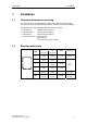
Issue 10/06 1 Installation 1 Installation 1.1 Clearance distances for mounting The inverters can be mounted adjacent to each other. When mounting inverters one above the other, the specified environmental conditions must not be exceeded. Independent of this, these minimum distances must be observed. ¾ ¾ ¾ ¾ 1.
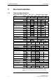
2 Electrical Installation Issue 10/06 2 Electrical Installation 2.1 Technical Specifications Input voltage range 3 AC 380 V – 480 V, ± 10 % Order No. 6SE6430- 2AD275CA0 Frame Size [kW] [hp] [kVA] [A] [A] [A] Output Rating (VT) Output Power VT-Input Current 1) VT-Output Current max. Fuse ded For UL specified Input Cable, min. Input Cable, max. Output Cable, min. Output Cable, max.
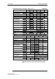
Issue 10/06 2 Electrical Installation Input voltage range 3 AC 380 V – 480 V, ± 10 % Order No. 6SE6430- 2UD275CA0 [kW] [hp] [kVA] [A] [A] [A] 3NA 3NE 2 [mm ] [AWG] 2 [mm ] [AWG] 2 [mm ] [AWG] 2 [mm ] [AWG] [Nm] [lbf.in] 7,5 10,0 10,1 17,3 19,0 20 3807 * 2,5 14 10,0 8 2,5 14 10,0 8 Frame Size Output Rating (VT) Output Power VT-Input Current 1) VT-Output Current max. Fuse Recommended For UL specified Input Cable, min. Input Cable, max. Output Cable, min. Output Cable, max.
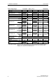
2 Electrical Installation Issue 10/06 Input voltage range 3 AC 380 V – 480 V, ± 10 % Order No.
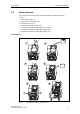
Issue 10/06 2.2 2 Electrical Installation Power terminals You can gain access to the mains and motor terminals by removing the front covers. ¾ ¾ ¾ ¾ ¾ ¾ ¾ Frame Size C (Fig. 2-1) Frame sizes D and E (Fig. 2-2) Frame Size F (Fig. 2-3) Frame Sizes FX and GX (Fig. 2-4) Connection terminals for Frame Sizes C -F (Fig. 2-5) Connection overview for Frame Size FX (Fig. 2-6) Connection overview for Frame Size GX (Fig. 2-7) Frame Size C " ! # Fig.
2 Electrical Installation Issue 10/06 Frame Sizes D and E 1 2 3 Fig.
Issue 10/06 2 Electrical Installation Frame Size F 1 2 19 mm 3 Fig.
2 Electrical Installation Issue 10/06 Frame Sizes FX and GX 1 3 Fig.
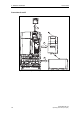
Issue 10/06 2 Electrical Installation Access to the power supply and motor terminals is possible by removing the front covers. Fig.
2 Electrical Installation Issue 10/06 Hoisting eyes Shield connection Mains cable PE Cable opening for mains conection U1/L1, V1/L2, W1/L3 Mains cable Phase U1/L1, V1/L2, W1/L3 Connection to Y-Capacitor Connection DCPA, DCNA Top adjustment rail Top retaining screw Connection DCPS, DCNS Status Display Panel Elektronic box Bottom adjustment rail Bottom retaining screw Fan screws Fan Shield connection control leads Fan fuses Transformer adaption Motor cable Phase U2, V2, W2 Motor cable PE Shield conne
Issue 10/06 2 Electrical Installation Hoisting eyes Shield connection Mains cable PE Cable opening for mains conection U1/L1, V1/L2, W1/L3 Mains cable Phase U1/L1, V1/L2, W1/L3 Connection to Y-Capacitor Connection DCPA, DCNA Top adjustment rail Top retaining screw Connection DCPS, DCNS Status Display Panel Elektronic box Bottom adjustment rail Bottom retaining screw Fan screws Fan Shield connection control leads Fan fuses Transformer adaption Motor cable Phase U2, V2, W2 Motor cable PE Shield conne
2 Electrical Installation 2.3 Issue 10/06 Control terminals Possible cable diameter: 0.08 - 2.5 mm2 (AWG: 28 - 12) Terminal Designation Function 1 – Output +10 V 2 – Output 0 V 3 ADC1+ Analog input 1 (+) 4 ADC1– Analog input 1 (–) 5 DIN1 Digital input 1 6 DIN2 Digital input 2 7 DIN3 Digital input 3 8 DIN4 Digital input 4 9 – Isolated output +24 V / max.
Issue 10/06 2 Electrical Installation 2.4 Block diagram PE 3 AC 380 - 480 V PE +10 V 1 L/L1, N/L2,L3 or L1, L2, L3 0V 2 ADC1+ 3 ADC1- BOP link A/D 4 RS232 ADC2+ 10 ADC2- A/D 150.00 Hz I 11 External 24 V 0 DIN1 DIN1 5 5 6 6 7 7 8 8 Fn Jog ~ Opto Isolation DIN2 DIN2 DIN3 DIN3 DIN4 DIN4 DIN5 DIN5 16 16 17 17 P BOP-2 = Frame sizes C to F B+/DC+ DC- DIN6 DIN6 Output +24 V max. 100 mA (isolated) Output 0 V max.
3 Factory setting 3 Issue 10/06 Factory setting The MICROMASTER 430 frequency inverter is set in the factory so that it can be operated without any additional parameterization. To do this, the motor parameters set in the factory (P0304, P0305, P0307, P0310), that correspond to a 4-pole 1LA7 Siemens motor, must match the rated data of the connected motor (refer to the rating plate). Further factory setting: ¾ Command sources P0700 = 2 (Digital input, see Fig.
Issue 10/06 4 Communications 4 Communications 4.1 Establishing communications MICROMASTER 430 ⇔ STARTER The following optional components are additionally required in order to establish communications between STARTER and MICROMASTER 430: ¾ PC <-> frequency inverter connecting set ¾ BOP-2 if the USS standard values (refer to Section 6.3.
4 Communications 4.
Issue 10/06 5 BOP-2 (Option) 5 BOP-2 (Option) 5.1 Buttons and their Functions Panel/ Button Function Indicates Status Start inverter Effects The LCD displays the settings currently used by the inverter. Pressing the button starts the inverter. This button is disabled by default. Activate the button: P0700 = 1 or P0719 = 10 ... 16 OFF1 Stop inverter Manual mode Automatic mode Functions OFF2 Pressing the button causes the motor to come to a standstill at the selected ramp down rate.
5 BOP-2 (Option) Issue 10/06 CAUTION A MICROMASTER 430 can only be operated using the BOP-2. If an attempt is made to use either a BOP or AOP, then 5.
Issue 10/06 6 Commissioning 6 Commissioning 6.1 Quick commissioning The frequency inverter is adapted to the motor using the quick commissioning function and important technological parameters are set. The quick commissioning shouldn't be carried-out if the rated motor data saved in the frequency inverter (4-pole 1LA Siemens motor, star circuit configuration frequency inverter (FU)specific) match the rating plate data.
6 Commissioning Issue 10/06 FU-spec. P0304 =... P0304 =... Rated motor voltage (Nominal motor voltage [V] from rating plate) The rated motor voltage on the rating plate must be checked, regarding the star/delta circuit configuration to ensure that it matches with the circuit connection configured at the motor terminal board P0305 =... P0305 =... Rated motor current (Nominal motor current [A] from rating plate) P0310 P0304 FU-spec. FU-spec. P0307 P0305 P0307 =... P0307 =...
Issue 10/06 6 Commissioning BOP Terminals USS BOP link P0700 = 2 Sequence control USS COM link CB COM link Setpoint channel Motor control 2 P1000 =... Selection of frequency setpoint * Enters the frequency setpoint source (also refer to Section 6.3.5). 1 MOP setpoint 2 Analog setpoint 3 Fixed frequency 4 USS on BOP-2 link 5 USS on COM link (control terminals 29 and 30) 6 CB on COM link (CB = communications module) 7 Analog setpoint 2 P1080 =... 0.00 Hz Min.
6 Commissioning 0 P1300 =... Control mode (enters the required control mode) 0 V/f with linear characteristic 1 V/f with FCC 2 V/f with parabolic characteristic 3 V/f with programmable characteristic 5 V/f for textile applications 6 V/f with FCC for textile applications 19 V/f control with independent voltage setpoint P1910 = ...
Issue 10/06 6.2 6 Commissioning Motor data identification START Factory setting P0625 = ? | Motor temp. - P0625| ≤ 5 °C ? yes no Ambient motor temperature (entered in °C) 20 °C The motor ambient temperature is entered at the instant that motor data is being determined (factory setting: 20 °C). The difference between the motor temperature and the motor ambient temperature P0625 must lie in the tolerance range of approx. ± 5 °C.
6 Commissioning 6.3 Issue 10/06 Commissioning the application An application is commissioned to adapt/optimize the frequency inverter - motor combination to the particular application. The frequency inverter offers numerous functions - but not all of these are required for the particular application. These functions can be skipped when commissioning the application. A large proportion of the possible functions are described here; refer to the parameter list for additional functions.
Issue 10/06 6.3.3 6 Commissioning Digital input (DIN) P0701 = ... Function digital input 1 Terminal 5 1 P0702 = ... Function digital input 2 Terminal 6 12 P0703 = ... Function digital input 3 Terminal 7 9 P0704 = ... Function digital input 4 Terminal 8 15 P0705 = ... Function digital input 5 Terminal 16 15 P0706 = ...
6 Commissioning 6.3.4 Issue 10/06 Digital outputs (DOUT) P0731 = ... BI: Function of digital output 1 * Defines source of digital output 1. 52.3 Common Settings: P0732 = ... BI: Function of digital output 2 * Defines source of digital output 2. 52.7 52.0 52.1 52.2 Drive ready Drive ready to run Drive running 0 0 0 P0733 = ... BI: Function of digital output 3 * Defines source of digital output 3. 0.0 r0747 = ...
Issue 10/06 6 Commissioning Selection of frequency setpoint P1000 =... Selection of frequency setpoint 0 No main setpoint 1 MOP setpoint 2 Analog setpoint 3 Fixed frequency 4 USS on BOP-2 link 5 USS on COM link 6 CB on COM link 7 Analog setpoint 2 10 No main setpoint + MOP setpoint 11 MOP setpoint + MOP setpoint 12 Analog setpoint + MOP setpoint 2 ... 6.3.
6 Commissioning 6.3.6 P0756 = ... Issue 10/06 Analog input (ADC) 0 ADC type Defines the analog input type and activates the monitoring function of the analog input.
Issue 10/06 6.3.7 6 Commissioning Analog output (DAC) 21 P0771 = ... CI: DAC Defines function of the 0 - 20 mA analog output.
6 Commissioning 6.3.8 Issue 10/06 Motor potentiometer (MOP) P1031 =... 0 Setpoint memory of the MOP Saves last motor potentiometer setpoint (MOP) that was active before OFF command or power down. 0 MOP setpoint will not be stored 1 MOP setpoint will be stored (P1040 is updated) P1032 =... Inhibit negative MOP setpoints 0 Neg. MOP setpoint is allowed 1 Neg. MOP setpoint inhibited P1040 =... Setpoint of the MOP Determines setpoint for motor potentiometer control. 1 5.
Issue 10/06 6 Commissioning P1001 = ... Fixed frequency 1 Can be directly selected via DIN1 (P0701 = 15, 16) 0.00 Hz P1002 = ... Fixed frequency 2 Can be directly selected via DIN2 (P0702 = 15, 16) 5.00 Hz P1003 = ... Fixed frequency 3 Can be directly selected via DIN3 (P0703 = 15, 16) 10.00 Hz P1004 = ... Fixed frequency 4 Can be directly selected via DIN4 (P0704 = 15, 16) 15.00 Hz P1005 = ... Fixed frequency 5 Can be directly selected via DIN5 (P0705 = 15, 16) 20.00 Hz P1006 = ...
6 Commissioning 6.3.10 Issue 10/06 Ramp function generator (RFG) P1091 = ... Skip frequency 1 (entered in Hz) 0.00 Hz Defines skip frequency 1, which avoids effects of mechanical resonance and suppresses frequencies within +/- p1101 (skip frequency bandwidth). P1092 = ... Skip frequency 2 0.00 Hz P1093 = ... Skip frequency 3 0.00 Hz P1094 = ... Skip frequency 4 0.00 Hz P1101 = ... Skip frequency bandwidth (entered in Hz) 2.00 Hz P1120 = ...
Issue 10/06 6.3.11 6 Commissioning Reference/limit frequencies P1080 = ... 0.00 Hz Min. frequency (entered in Hz) Sets minimum motor frequency [Hz] at which motor will run irrespective of frequency setpoint. If the setpoint falls below the value of p1080, then the output frequency is set to p1080 taking into account the sign. P1082 = ... 50.00 Hz Max. frequency (entered in Hz) Sets maximum motor frequency [Hz] at which motor will run irrespective of the frequency setpoint.
6 Commissioning 6.3.12 P0290 = ... Issue 10/06 Inverter protection Inverter monitoring r0036 i2t P0294 r0037 Heat sink temperature P0292 Inverter overload reaction P0290 A0504 i_max control A0505 A0506 F0004 f_pulse control IGBT temperature P0292 P0292 =... 0 Inverter overload reaction Selects reaction of inverter to an internal over-temperature.
Issue 10/06 6.3.13 6 Commissioning Motor protection In addition to the thermal motor protection, the motor temperature is also included in the adaptation of the motor equivalent circuit diagram data. For MM430 the motor temperature can only be measured using a KTY84 sensor. For the parameter setting P0601 = 0,1, the motor temperature is calculated / estimated using the thermal motor model.
6 Commissioning 6.3.14 P0400 =... Issue 10/06 Encoder 0 Select encoder type The table shows the values of P0400 as a function of the Selects the encoder type. number of tracks: 0 Inhibited Parameter Terminal Track Encoder output 1 Single-track pulse encoder 2 Two-track pulse encoder single ended P0400 = 1 A For hoisting gear applications (4-quadrant operation!), a 2-track encoder must be used.
Issue 10/06 6.3.15 6 Commissioning V/f control P1300 =... 0 Control mode The control type is selected using this parameter. For the "V/f characteristic" control type, the ratio between the frequency inverter output voltage and the frequency inverter output frequency is defined. 0 V/f with linear 1 V/f with FCC 2 V/f with parabolic characteristic 3 V/f with programmable characteristic (→ P1320 – P1325) P1310 =... 50.
6 Commissioning Issue 10/06 P1312 =... 0.0 % Starting boost (entered in %) Voltage boost when starting (after an ON command) when using the linear or square-law V/f characteristic as a % relative to P0305 (rated motor current) or P0350 (stator resistance). The voltage boost remains active until 1) the setpoint is reached for the first time and 2) the setpoint is reduced to a value that is less than the instantaneous ramp-function generator output. P1320 =... Programmable V/f freq. 0.0 Hz coord.
Issue 10/06 6 Commissioning 6.3.16 Inverter-specific Functions 6.3.16.1 Flying start 0 P1200 = ... Flying start Starts inverter onto a spinning motor by rapidly changing the output frequency of the inverter until the actual motor speed has been found.
6 Commissioning 6.3.16.
Issue 10/06 6 Commissioning 52.3 P0731=52.C BI: Fct digital output 1 Defines the source for digital output 1. NOTE The brake relay can also be controlled from another digital output (if this is available) or using a distributed I/O module. Analog to DOUT 1, it should be guaranteed that the I/Os are controlled by the status bit “MHB active”. P0748 = 0 Frequent settings: 52.0 52.1 52.2 52.3 52.4 52.5 52.6 52.7 52.8 52.9 52.A 52.B 52.C 52.D 52.E 52.F 53.0 53.
6 Commissioning 6.3.16.4 P1230 = ... Issue 10/06 DC brake BI: Enabling the DC brake This enables DC braking using a signal that was used from an external source. The function remains active as long as the external input signal is active. DC braking causes the motor to quickly stop by injecting a DC current BI: Enable DC brk. 1 P1230.
Issue 10/06 6 Commissioning 2 ON OFF1/OFF3 t P0347 OFF2 t ⏐f⏐ OFF ramp OFF2 P1234 DC braking OFF2 t DC braking active r0053 1 Bit00 0 P1234 =... 6.3.16.5 P1236 =... t P1233 650 Hz DC braking start frequency (entered in Hz) Sets the start frequency for the DC brake. Compound braking 0% Compound braking current (entered in %) Defines DC level superimposed on AC waveform after exceeding DC-link voltage threshold of compound braking.
6 Commissioning 6.3.16.6 Issue 10/06 Vdc controller 1 P1240 =... Configuration of Vdc controller Enables / disables Vdc controller. 0 Vdc controller disabled 1 Vdc-max controller enabled P1254 =... 1 Auto detect Vdc switch-on levels Enables/disables auto-detection of switch-on levels for Vdc control functionalities. 0 Disabled 1 Enabled VDC r1242 VDC_max -controller active r0056 Bit14 t A0911 1 0 t ⏐f⏐ fact fset t 6.3.16.
Issue 10/06 6 Commissioning BI: Fct. of DOUT 1 P0731.C (52:3) 1 0 f fmax+ 2f Slip t P1264 P1263 f Flying start f Mains fset,Inverter f Motor t r1261 1 Bit00 0 t r1261 1 Bit01 0 t P1262 r1261 BO: Bypass status word Output word from the bypass feature that allows external connections to be made. Bit00 Bit01 P1262 = ... P1263 = ... P1264 = ... P1265 = ... P1266 = ... P1262 Motor supplied by inverter Motor supplied by mains 0 0 NO NO 1 1 YES YES 1.
6 Commissioning 6.3.16.8 Issue 10/06 Load torque monitoring This function monitors the transmission of force between a motor and driven load within a defined frequency range. Typical applications include, for example, detecting when a transmission belt breaks or detecting when a conveyor belt is in an overload condition. For the load torque monitoring, the actual frequency/torque actual value is compared to a programmed frequency/torque characteristic (refer to P2182 – P2190).
Issue 10/06 6 Commissioning |Torque| [Nm] P1080 Min. frequency P1082 Max.
6 Commissioning 6.3.16.9 Issue 10/06 PID controller Process values can be controlled via PID control (e.g. pressure, liquid level). The process setpoint (PID setpoint) can be a fixed setpoint (e.g. PID-FF) or an analog setpoint (e.g. analog input). The current value of the process is determined by a sensor, which is connected to the inverter via an analog input. NOTE • PID-FF or PID-MOP are build up like FF (refer to Section 6.3.9) or MOP (refer to Section 6.3.8).
Issue 10/06 6 Commissioning PID SUM PID RFG USS BOP link USS COM link P2264 CB COM link P2200 PID PT1 PID PT1 PID SCL P2265 P2271 P2285 P2280 P2253 P2261 PID FF P2270 P2254 P2269 ADC P2257 PID MOP P2258 PID controller structure 0 PID − ∆PID 1 Motor control PIDOutput ADC2 Example Parameter Parameter text Example P2200 P2253 P2264 P2267 P2268 P2280 P2285 P2291 P2292 BI: Enable PID controller CI: PID setpoint CI: PID feedback Max. PID feedback Min.
6 Commissioning Issue 10/06 Mains Mains PressureSensor Sensor Pressure Inverter Inverter MotorStarters Starters Motor To Inverter PID Input To Inverter PID Input MV M1 M2 MV - Variable speed motor M1 - Motor switched with relay 1 M3 M2 - Motor switched with relay 2 M3 - Motor switched with relay 3 By default the motor starters are controlled from relay outputs (DOUT1,2,3).
Issue 10/06 P2372 = ... P2373 = ... P2374 = ... P2375 = ... P2376 = ... P2377 = ... P2378 = ... 6 Commissioning 0 Motor staging cycling Enables motor cycling for the motor staging feature. 0 Disabled 1 Enabled When activated (P2372 = 1), then the selection of the motor, that is to be switched-in or switched-out, depends initially on the operating hours counter P2380.
6 Commissioning Issue 10/06 Destaging: f f act P2378 P1082 ⋅ 100 f set P1080 tx t P1120 % ∆PID t -P2373 P2375 r2379 Bit02 1 0 Bit01 1 0 Bit00 1 0 t Condition for destaging: a b c r2379 ⎛ P2378 P1080 ⎞ − tx = ⎜⎜ ⎟ ⋅ P1120 P1082 ⎟⎠ ⎝ 100 CO/BO: Motor staging status word Output word from the motor staging feature that allows external connections to be made. Bit00 Bit01 Bit02 P2380 = ...
Issue 10/06 6 Commissioning PID feedback (Sensor) % PID setpoint P2392 t f ∆PID fset, PID setpoint f Motor f Restart P2390 [Hz] P1080 P2391 PID active fRestart = P2000 ⋅ P2390 + 5% 100 % P2390 [Hz] = P2000 ⋅ P2390 100 % tx t ty Energy saving mode active PID active P1080 ⋅ P1121 P1082 fRestart ⋅ P1120 ty = P1082 tx = NOTE If energy saving setpoint is 0, the energy saving function is disabled.
6 Commissioning Issue 10/06 6.3.16.12 Free function blocks (FFB) P2800 =... 0 Enable FFBs Parameter P2800 is used to activate all free function blocks (generally, P2800 is set to 1). Possible settings: 0 Inhibited 1 Enabled P2801 =... 0.0 Activate FFBs Parameter P2801 is used to individually enable (activate) the free function blocks P2801[0] to P2801[16] (P2801[x] > 0). Further, parameters P2801 and P2802 are used to define the chronological sequence of all of the function blocks.
Issue 10/06 6 Commissioning FFB Input parameters Output parameters AND1 AND2 AND3 P2810[2] P2812[2] P2814[2] BI: AND 1 BI: AND 2 BI: AND 3 r2811 r2813 r2815 BO: AND 1 BO: AND 2 BO: AND 3 – – – OR1 OR2 OR3 P2816[2] P2818[2] P2820[2] BI: OR 1 BI: OR 2 BI: OR 3 r2817 r2819 r2821 BO: OR 1 BO: OR 2 BO: OR 3 – – – XOR1 XOR2 XOR3 P2822[2] P2824[2] P2826[2] BI: XOR 1 BI: XOR 2 BI: XOR 3 r2823 r2825 r2827 BO: XOR 1 BO: XOR 2 BO: XOR 3 – – – NOT1 NOT2 NOT3 P2828 P2830 P2832 BI: NOT 1 BI: NOT
6 Commissioning 6.3.17 Issue 10/06 Data sets For many applications, it is advantageous, if several parameter settings can be simultaneously changed during operation or during operational readiness using an external signal. By using indexing, different settings can be saved under one parameter. These are then activated when the data set is changed-over.
Issue 10/06 6 Commissioning Example for CDS changeover: CDS1: Command source via terminals and setpoint source via analog input (ADC) CDS2: Command source via BOP-2 and setpoint source via MOP CDS changeover is realized using digital input 4 (DIN 4) Steps: 1. Carry-out commissioning for CDS1 (P0700[0] = 2 and P1000[0] = 2) 2. Connect P0810 (P0811 if required) to the CDS changeover source (P0704[0] = 99, P0810 = 722.3) 3. Copy from CDS1 to CDS2 (P0809[0] = 0, P0809[1] = 1, P0809[2] = 2) 4.
6 Commissioning Issue 10/06 Example: 1. Commissioning steps with a motor: − Carry-out commissioning at DDS1. − Connect P0820 (P0821 if required) to the DDS changeover source (e.g. using DIN 4: P0704[0] = 99, P0820 = 722.3). − Copy DDS1 to DDS2 (P0819[0] = 0, P0819[1] = 1, P0819[2] = 2). − Adapt DDS2 parameters (e.g. ramp-up / ramp-down times P1120[1] and P1121[1]). ADC Sequence control SUM setpoint AFM Motor control RFG Gating unit DIN M P0820 = 722.
Issue 10/06 6.3.18 6 Commissioning Diagnostic parameters r0021 CO: Act. filtered frequency Displays actual inverter output frequency (r0021) excluding slip compensation, resonance damping and frequency limitation. r0022 Act. filtered rotor speed Displays calculated rotor speed based on inverter output frequency [Hz] x 120 / number of poles. r0022 [1/min] = r0021 [Hz] ⋅ r0032 60 r0313 CO: Act. filtered power Displays motor power (power output at the motor shaft).
6 Commissioning r0054 r0063 Issue 10/06 CO/BO: Control word 1 Displays the first control word (STW) of the frequency inverter and can be used to display the active commands.
Issue 10/06 6.4 6 Commissioning Series commissioning An existing parameter set can be transferred to a MICROMASTER 430 frequency inverter using STARTER or DriveMonitor (refer to Section 4.1 "Establishing communications MICROMASTER 430 ⇔ STARTER"). Typical applications for series commissioning include: 1. If several drives are to be commissioned that have the same configuration and same functions. A quick / application commissioning (first commissioning) must be carried-out for the first drive.
7 Displays and messages Issue 10/06 7 Displays and messages 7.1 LED status display LEDs for indicating the drive state OFF ON approx. 0.3 s, flashing approx.
Issue 10/06 7.2 7 Displays and messages Fault messages and Alarm messages Fault Significance Alarm Significance F0001 Overcurrent A0501 Current Limit F0002 Overvoltage A0502 Overvoltage limit F0003 Undervoltage A0503 Undervoltage Limit F0004 Inverter Overtemperature A0504 Inverter Overtemperature 2 F0005 Inverter I t A0505 Inverter I2t F0011 Motor Overtemperature I2t A0511 Motor Overtemperature I2t F0012 Inverter temp.
Information about MICROMASTER 430 is also available from: Regional Contacts Please get in touch with your contact for Technical Support in your Region for questions about services, prices and conditions of Technical Support. Central Technical Support The competent consulting service for technical issues with a broad range of requirements-based services around our products and systems. Europe / Africa Tel: +49 (0) 180 5050 222 Fax: +49 (0) 180 5050 223 Email: adsupport@siemens.