
Operating instructions


6 Commissioning Issue 10/06
MICROMASTER 430
42 Operating Instructions (Compact)
P1312 =...
Starting boost (entered in %)
Voltage boost when starting (after an ON command) when using the linear or square-law
V/f characteristic as a % relative to P0305 (rated motor current) or P0350 (stator
resistance). The voltage boost remains active until
1) the setpoint is reached for the first time and
2) the setpoint is reduced to a value that is less than the instantaneous ramp-function
generator output.
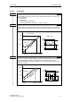
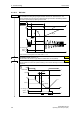
P1320 =...
Programmable V/f freq.
coord. 1
Sets V/f coordinates
(P1320/1321 to P1324/1325) to
define V/f characteristic.
P1321 =...
Programmable. V/f volt.
coord. 1
P1322 =...
Programmable V/f freq.
coord. 2
P1323 =...
Programmable V/f volt.
coord. 2
P1324 =...
Programmable V/f freq.
coord. 3
P1325 =...
Programmable V/f volt.
coord. 3
]P0304[V
100[%]
r0395[%]
100[%]
P1310[%]
P1310[V] ⋅⋅=
V
P1325
f1
P1320
f
max
P1082
V
max
r0071
V
n
P0304
P1323
P1321
P1310
f0
0 Hz
f2
P1322
f3
P1324
f
n
P0310
f
V
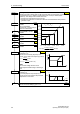
max
= f(V
dc
, M
max
)
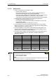
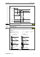
Starting frequency for FCC
(entered as a %)
Defines the FCC starting frequency as a
function of the rated motor frequency (P0310).
1333P
100
P0310
f
FCC
⋅=
()
%61333P
100
P0310
f
HysFCC
+⋅=
+
NOTE
The constant voltage boost P1310 is
continually decreased analog to switching-in
FCC.
f
FCC
f
f
FCC+Hys
FCC
V/f
Switch-over
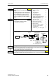
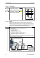
Slip compensation
(entered in %)
Dynamically adjusts output frequency of
inverter so that motor speed is kept constant
independent of motor load.
f
f
N
out
6 % 10 %
P1335
100 %
%
Range of slip compensation :
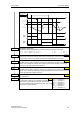
P1338 =...
Resonance damping gain V/f
Defines resonance damping gain for V/f.
P1335 = ...
0.0 %
P1333 = ...
10.0 %
0.0 %
0.0 Hz
0.0 Hz
0.0 Hz
0.0 Hz
0.0 Hz
0.0 Hz
0.00