
Operating instructions


Issue 10/06 6 Commissioning
MICROMASTER 430
Operating Instructions (Compact)
49
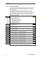
f
t
P1264
0
1
0
1
P1263
0
1
P1262 P1262
t
t
t
r1261
Bit00
r1261
Bit01
Mains
f
f
Motor
f
max
+ 2f
Slip
(52:3)
B
I: Fct. of DOUT 1
P0731.C
f
Flying start
set,Inverter
f
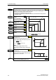
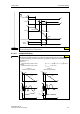
BO: Bypass status word
Output word from the bypass feature that allows external connections to be made.
Bit00 Motor supplied by inverter 0 NO 1 YES
Bit01 Motor supplied by mains 0 NO 1 YES
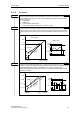
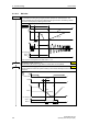
Bypass dead time
P1262 is the interlock time between switching one contactor OFF, and the other ON. Its
minimum value should not be smaller than the motor demagnetization time P0347.
De-Bypass time
This delay timer is used as a delay for all sources of switchover from bypass to inverter
control. If the condition for switching from bypass is removed then this timer is reset, and
must run through again before bypass will occur.
Bypass time
This delay timer is used as a delay for all sources of switchover from inverter control to
bypass. If the condition for switching to bypass is removed then this timer is reset, and must
run through again before bypass will occur.
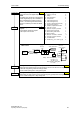
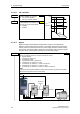
Bypass frequency
Bypass frequency.
BI: Bypass command
Bypass Control P1260 can be controlled by an external
switch which is connected to the inverter. The P1266 BI:
Bypass command selects the interface (e.g. DIN, USS or CB)
from which the signal originates.
722.0 = Digital input 1
722.1 = Digital input 2
722.2 = Digital input 3
722.3 = Digital input 4
722.4 = Digital input 5
722.5 = Digital input 6
722.6 = Digital input 7
722.7 = Digital input 8
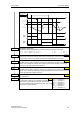
r1261
1.000 s
P1262 = ...
1.0 s
P1263 = ...
1.0 s
P1264 = ...
50.00 Hz
P1265 = ...
0.0
P1266 = ...