
Operating instructions


Issue 10/06 1 Installation
MICROMASTER 430
Operating Instructions (Compact)
5
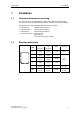
1 Installation
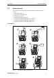
1.1 Clearance distances for mounting
The inverters can be mounted adjacent to each other. When mounting inverters
one above the other, the specified environmental conditions must not be exceeded.
Independent of this, these minimum distances must be observed.
¾ Frame Size C above and below 100 mm
¾ Frame Size D, E above and below 300 mm
¾ Frame Size F above and below 350 mm
¾ Frame Size FX, GX above 250 mm
below 150 mm
in front 40 mm (FX), 50 mm (GX)
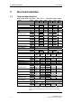
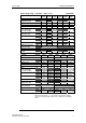
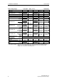
1.2 Mounting dimensions
Frame Drilling Dimensions Tightening Torque
Size
H
mm (Inch)
W
mm (Inch)
Bolts Nm (lbf.in)
C
204
(8.03)
174
(6.85)
4 x M5
2,5
(22.12)
D
486
(19.13)
235
(9.25)
4 x M8
E
616,4
(24.27)
235
(9.25)
4 x M8
F
810
(31.89)
300
(11.81)
4 x M8
3,0
(26.54)
FX
1375,5
(54.14)
250
(9.84)
6 x M8
13,0
(115.02)
H
W
GX
1508,5
(59.38)
250
(9.84)
6 x M8
13,0
(115.02)
Fig. 1-1 Mounting dimensions