8600 Series and CTP-NB Service and Installation Manual Please read this manual completely before attempting to install or operate this equipment! Notify carrier of damage! Inspect all components immediately. See page 2.
18600 and CTP-NB Series Service and Installation Manual Contents Receiving & Inspecting Equipment....................................................... 2 Specifications......................................................................................... 3 Refrigerant Charges............................................................................... 4 Installation ............................................................................................. 4 Operation 18600PTBM & PTL Series........
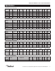
18600 and CTP-NB Series Service and Installation Manual Specifications 18600PTBM Pizza tables with raised rail Model 1/3 Pan Size Capacity # Of Doors # Of Shelf Max Shelf Area Storage Shelves Load (LBS) FT2 Cap. FT3 BTU Load Base/Rail BTU Sys. Cap. Base/Rail H.P. Voltz/Hertz/ Phase Amps NEMA Plug Ship Weight LBS/KG 18648PTBM 6 (1) 27” 1 124 3.95 10.23 470/441 2001/952 1/4 115/60/1 10.0 5-15P 520/236 18660PTBM 7 19” & 27” 2 70/124 6.51 15.
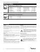
18600 and CTP-NB Series Service and Installation Manual Refrigerant Charges Refrigerant Charges For 18600 Series Units: 18648-PTBM & PTL . . . . . . . . . . 16 oz. (454g) 18660-PTBM . . . . . . . . . . . . . . . 24 oz. (680g) 18672-PTBM & PTL . . . . . . . . . . 32 oz. (907g) 18691-PTBM . . . . . . . . . . . . . . . 32 oz. (907g) 18699-PTBM & PTL . . . . . . . . . . 32 oz. (907g) 186114-PTBM . . . . . . . . . . . . . 48 oz. (1361g) 18648-BUCM & BSTM . . . . . . . . 16 oz. (454g) 18660-BUCM & BSTM . . . .
18600 and CTP-NB Series Service and Installation Manual Operation: 18600PTBM & PTL Series Product should be loaded into the unit with care. Failure to heed these recommendations could result in damage to the interior of the cabinet or the blower coil. This unit is equipped with two on/off switches located behind the louvered machine compartment panel. The unit’s compressor and all evaporator fans will begin operating when the main power switch is turned to the ON position.
18600 and CTP-NB Series Service and Installation Manual Operation: 18600PDL Series Product should be loaded into the unit with care. Failure to heed these recommendations could result in damage to the interior of the cabinet or the blower coil. This unit is equipped with two on/off switches located behind the louvered machine compartment panel. The unit’s compressor and all evaporator fans will begin operating when the main power switch is turned to the ON position.
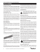
18600 and CTP-NB Series Service and Installation Manual Pressure Control Settings The factory recommended low-pressure control settings for 18600PTBM’s are: 55psi cut-in and 30psi cut-out to maintain proper temperature for product in the rail. The interior temperature is controlled by the thermostat mounted in the mechanical compartment. The factory recommended low-pressure control settings for 18600PTL’s are: 20psi (1.38bar) cut-in and 10psi (0.70bar) cut-out.
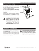
18600 and CTP-NB Series Service and Installation Manual Care & Cleaning Door Gasket Maintenance Door gaskets require regular cleaning to prevent mold and mildew build up and also to retain the elasticity of the gasket. Gasket cleaning can be done with the use of warm soapy water. Avoid full strength cleaning products on gaskets as this can cause them to become brittle and crack. Never use sharp tools or knives to scrape or clean the gasket.
18600 and CTP-NB Series Service and Installation Manual Care & Cleaning, continued If conditions are such that the condenser is totally blocked in three months, the frequency of cleaning should be increased. Clean the condenser with a vacuum cleaner or stiff brush. If extremely dirty, a commercially available condenser cleaner may be required. Continuous opening and closing of the doors will hamper the unit’s ability to maintain optimum refrigeration temperature.
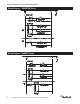
18600 and CTP-NB Series Service and Installation Manual Wiring Diagram - 18600PTBM Series Wiring Diagram - 18600PTL Series 10 For customer service, call (800) 733-8829, (800) 773-8821, Fax (989) 773-3210, www.delfield.
18600 and CTP-NB Series Service and Installation Manual Wiring Diagram - 18600bucM & bstM Series Wiring Diagram - 18600PDL Series For customer service, call (800) 733-8829, (800) 773-8821, Fax (989) 773-3210, www.delfield.
18600 and CTP-NB Series Service and Installation Manual Wiring Diagram - ctp-nb series N L1 POWER SWITCH CONDENSING UNIT TEMPERATURE CONTROLS THE CONDENSING UNIT 12 For customer service, call (800) 733-8829, (800) 773-8821, Fax (989) 773-3210, www.delfield.
18600 and CTP-NB Series Service and Installation Manual 18600PTBM Replacement Parts All 18600PTBM Models 3234290 1" Shelf Support 9321132 1.
18600 and CTP-NB Series Service and Installation Manual 18600BUCM Replacement Parts All 18600BUCM Models 3234290 1" Shelf Support 9321132 1.
18600 and CTP-NB Series Service and Installation Manual 18600BSTM & 18600PTL Replacement Parts All 18600BSTM Models 3234290 1" Shelf Support 9321132 1.
18600 and CTP-NB Series Service and Installation Manual CTP8000-NB & 18600PDL Replacement Parts All CTP8000-NB Models 243-ALS-0032 Divider, Bar, Cold 3234392 Hinge, Pan Cover, Center 3234282 Hinge, Pan Cover, End, LH 3234266 Hinge, Pan Cover, End, RH 9321374 Pin, Hinge, Salad Pan *000-254-Z000B Condenser Assembly, 1/5HP, CTP-8100 *000-AUX-0038 Condensing Unit Assembly, 1/5HP, CTP *223-016-Z000P Cover, Hinged, CTP *265-016-003U Cover, Pan, Rail, 8 Pan *265-016-003W Cover, Pan, Rail, 12 Pa
18600 and CTP-NB Series Service and Installation Manual Replacement Parts - Control Assemblies Key 1 2 3 Part Number 000-282-006I 2193942 2190154 2194810 Key - Part Number 000-282-006C & 000-282-006D 2193927 2190154 2194810 1 2 3 Description Thermostat & Dual Pressure Control Assembly Dual pressure control Rocker switch, 20A/125V Control, Danfoss, GDM, 115V 1 2 3 Description Thermostat & Low Pressure Control Assembly 1 Low pressure control Rocker switch, 20A/125V Control, Danfoss, GDM, 115V 2
600 and CTP-NB Series Service and Installation Manual Replacement Parts - Condensing Unit Assemblies 4 1 3 2 5 6 Part Number Description 000-AUX-0038 Condensing Unit Assembly, 1/5HP, CTP 3526694 Compressor 3516082 Condenser Coil - 000-BN5-0031 Assembly, 1/5 Condensing Unit 3516172 Fan Blade 1 3516457 Fan Blade 2162691 Fan Motor 2 2160020 Fan Guard 031-264-0000 Fan Motor Bracket 3 2162717 Fan Motor 3516191 Filter Drier 4 3526997 Compressor, Danfoss, TF4CLS Temp Control
18600 and CTP-NB Series Service and Installation Manual Replacement Parts - Condensing Unit Assemblies 1 2 1 3 2 3 4 5 4 5 8 6 7 Key Part Number Description Key Part Number Description - 000-BN5-0036 Assembly, 3/4 HP Condenser, Med - 000-BN5-0037 Assembly, 1/3 Condensing Unit 1 2160019 Guard, Fan, Wire 1 3516457 Fan Blade 2 3516442 Capacitor, Start, Run, Assembly 2 2160020 Fan Guard 3 3527021 Compressor, 3/4 HP Med 3 3527000 Compress, Danfoss, NF7CLS 4 3516322 Dri
18600 and CTP-NB Series Service and Installation Manual Replacement Parts - Condensing Unit Assemblies 000-BN5-003Y Assembly, 1/2-1/5 Stacked 3516433 Blade, Fan, 25Deg, 10", CW 3516457 Blade, Fan, 7.25 DIA. 2194789 Capacitor, Start, 240MFD 2194787 Capacitor, Start, 280MFD 3516455 Coil, Cond., 1/2 HP 3516454 Coil, Cond., 1/5, 1/4 3526997 Comp, 1/5HP, 115/60, R404A 3527001 Comp, SC12CLX.
18600 and CTP-NB Series Service and Installation Manual Replacement Parts - Evaporator Coil Assembly Key 1 2 3 4 5 6 7 8 - Part Number 000-248-0030 2160024 2160023 3516095 030-232-0003 3516273 030-233-0001 075-231-0033 030-234-0003 2184317 2195551 Description Coil Assembly, R404A, Ref Guard, fan, 4.
18600 and CTP-NB Series Service and Installation Manual Replacement Parts - Door & Cover Assemblies 2 1 1 2 Key Part Number Description Part Number Description - 000-187-007X Assembly, Dr, Ref, 19X26, RT, 430 000-402-0054 Assembly, Hinged Cover, 6 Pan, PTL 1 1701183 Gasket, Dr, 19, Mark7 000-402-004Q Assembly, Hinged Cover, 6 Pan, RT 2 0160179 Hinge Kit 000-402-004V Assembly, Hinged Cover, 8 Pan - 000-187-007Y Assembly, Dr, Ref, 19X26, LT, 430 000-402-004U Assembly, Hinged Cover
18600 and CTP-NB Series Service and Installation Manual Standard Labor Guidelines To Repair Or Replace Parts On Delfield Equipment Advice and recommendations given by Delfield Service Technicians do not constitute or guarantee any special coverage. • A maximum of 1-hour is allowed to diagnose a defective component. • A maximum of 1-hour is allowed for retrieval of parts not in stock. • A maximum travel distance of 100 miles round trip and 2-hours will be reimbursed.
18600 and CTP-NB Series Service and Installation Manual Standard One Year Warranty (One year parts, 90 days labor.
18600 and CTP-NB Series Service and Installation Manual 18600PDL One Limited Year Warranty (One Year Parts And Labor) Delfield warrants to the Original Purchaser of the Delfield product (herein called the “Unit”) that such Unit, and all parts thereof, will be free from defects in material and workmanship under normal use and service for a period of one (1) year from the date of shipment of the Unit to the Original Purchaser or, if the Original Purchaser returns the warranty card completely filled out inclu
18600 and CTP-NB Series Service and Installation Manual Additional Four Year Protection Plan Delfield Model# Serial # (for Motor-Compressor only) Installation Date In addition to the Standard One Year Warranty on the MotorCompressor contained in the above listed Delfield product (the “Unit”), The Delfield Company (“Delfield”) also agrees to repair, or exchange with similar or interchangeable parts in design and capacity at Delfield’s option, the defective Motor-Compressor contained in the Unit (the “
18600 and CTP-NB Series Service and Installation Manual Notes For customer service, call (800) 733-8829, (800) 773-8821, Fax (989) 773-3210, www.delfield.
Covington, TN Mt. Pleasant, MI Thank you for choosing Delfield! Help is a phone call away. Help our team of professional, courteous customer service reps by having your model number and serial number available at the time of your call (800) 733-8829. Model:________________________ S/N: _______________________ Installation Date:________________ For a list of Delfield’s authorized parts depots, visit our website at www.delfield.com. Delfield ™ ® 980 S. Isabella Rd., Mt. Pleasant, MI 48858, U.S.A.