Delfield ™ ® 200 & 300 SERIES Service and Installation Manual Please read this manual completely before attempting to install or operate this equipment! Notify carrier of damage! Inspect all components immediately.
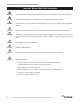
00 and 300 Series Service and Installation Manual Important Warning And Safety Information WARNING Read This Manual Thoroughly Before Operating, Installing, Or Performing Maintenance On The Equipment. WARNING Failure To Follow Instructions In This Manual Can Cause Property Damage, Injury Or Death. WARNING Do Not Store Or Use Gasoline Or Other Flammable Vapors Or Liquids In The Vicinity Of This Or Any Other Appliance.
200 and 300 Series Service and Installation Manual Contents Receiving And Inspecting Equipment......................................... 3 Serial Number Information......................................................... 4 Warramtu Information................................................................ 4 Regulatory Certifications............................................................. 4 Specifications.............................................................................. 5 Installation.....
200 and 300 Series Service and Installation Manual Serial Number Information Models Serial Tag Location N225, N227 On the compressor stand next to the temperature control 203, 204, 204P, 248, 250, 305 On the bottom of the ice chests 240 On the back 242 On the bottom of the sink 307 Underneath the top Always have the serial number of your unit available when calling for parts or service. ©2013 The Delfield Company. All rights reserved. Reproduction without written permission is prohibited.
200 and 300 Series Service and Installation Manual Specifications MODEL L D H SHIP CUTOUT SIZE WEIGHT N225 16.56” (42.1cm) 27.87” 26.75” 115lbs (70.8cm) (67.9cm) (52kg) N227 30” (76.2cm) 27.87” 26.75” 191lbs (70.8cm) (67.9cm) (87kg) CABINET H.P. CAPACITY AMP VOLT NEMA PLUG DESIGN LOAD BTU SYSTEM CAP. BTU EVAP BTU/ TD/TEMP 25.75” x 14.62” (65.4cm x 37.1cm) 6 gal. 1/5 5.3 115 5-15P 292 411 20/20°/-23° 25.75” x 28.00” (65.4cm x 71.1cm) 12 gal. 1/5 5.
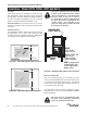
200 and 300 Series Service and Installation Manual Installation - Models N225, N225L, N227 And N227L Location Units in this manual are intended for indoor use only. The refrigeration system has been factory tested and should require no further adjustment during installation. For the most efficient refrigeration, be sure to provide good air circulation inside and outside the unit. Outside Cabinet: Be sure that the unit has access to ample air. Avoid hot corners and locations near stoves and ovens.
200 and 300 Series Service and Installation Manual Installation - Models 203, 204, 204P, 240, 242, 248, 250, 305 And 307 Location Drain Units in this manual are intended for indoor use only. Provided 1” (2.5cm) drain, nut and washer must be field installed to an appropriate container or floor drain following local code requirements. Sinks come standard with 1-1/2” basket strainer assemblies. Avoid hot corners and locations near stoves and ovens.
200 and 300 Series Service and Installation Manual Operation - Models N225, N225L, N227 And N227L After installation, the unit will begin operating simply by plugging it into the proper outlet. If the unit does not operate after being plugged in, check to see if the thermostat is in the OFF position. The models 225 and 227 are designed to hold frozen products at a temperature range of 5°F to -5°F (-15°C to -21°C). The thermostat is located in the machine compartment.
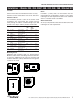
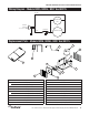
200 and 300 Series Service and Installation Manual Wiring Diagram - Models N225, N225L, N227 And N227L WH ITE CONDENSER FAN GREEN POWE R SUPPLY 115V/60 Hz/1 Ø BLACK CONTROL COM PRESSOR GND Replacement Parts - Models N225, N225L, N227 And N227L 4 3 5 6 2 1 10 7 9 8 12 11 Key Part No. Description Key Part No.
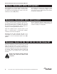
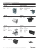
200 and 300 Series Service and Installation Manual Replacement Parts Model 203 000-AUO-0030 3234110 9321011 3234242 Models 204 And 204P Removable lid with handle Lid handle Lid handle screw Drain Removable lid Lid handle Lid handle screws Drain Model 248 3977953 3234088 3234242 000-AUO-0030 3234110 9321011 3234007 3234076 Basket Strainer Faucet Model 250 Guard Glass filler Drain Removable lid Lid handle Lid handle screw Model 305 3234242 000-AUO-0030 3234110 9321011 Glass filler 9.5” high, max.
200 and 300 Series Service and Installation Manual Standard Labor Guidelines To Repair Or Replace Parts On Delfield Equipment Advice and recommendations given by Delfield Service Technicians do not constitute or guarantee any special coverage. • A maximum of 1-hour is allowed to diagnose a defective component. • A maximum of 1-hour is allowed for retrieval of parts not in stock. • A maximum travel distance of 100 miles round trip and 2-hours will be reimbursed.
Delfield ™ ® Covington, TN Mt. Pleasant, MI Thank you for choosing Delfield! Help is a phone call away. Help our team of professional, courteous customer service reps by having your model number and serial number available at the time of your call (800) 733-8829. Model:________________________ S/N: _______________________ Installation Date:________________ For a list of Delfield’s authorized parts depots, visit our website at www.delfield.com Register your Delfield warranty online. Go to www.