500 Series Service and Installation Manual Please read this manual completely before attempting to install or operate this equipment! Notify carrier of damage! Inspect all components immediately. See page 2.
500 Series Display Cases Service and Installation Manual CONTENTS RECEIVING & INSPECTING EQUIPMENT..............................2 SPECIFICATIONS ..................................................................3 PRESSURE CONTROL SETTINGS.........................................5 INSTALLATION................................................................. 5, 6 OPERATION ..................................................................... 5, 6 CARE & CLEANING...............................................
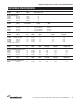
500 Series Display Cases Service and Installation Manual 500 SERIES SPECIFICATIONS MODEL NUMBER DELFIELD PART # VOLTS/HERTZ PHASE AMPS (includes lights & fan) 115/60/1 115/60/1 115/60/1 115/60/1 5.0 5.0 5.0 5.0 NUMBER OF 12 X 20 WELLS VOLTS/HERTZ PHASE AMPS 3 4 5 120, 208-240V/60/1 120, 208-240V/60/1 120, 208-240V/60/1 19.0/21.0 24.0/27.0 30.0/34.
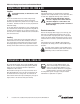
500 Series Display Cases Service and Installation Manual INSTALLATION: 500 CD, CR, CRR & OR Location To meet NSF standards, all units must be sealed to the floor. Be sure the location chosen has a floor strong enough to support the total weight of the cabinet and contents. Contents fully loaded in this product line can weigh as much as 1500 lbs. Reinforce the floor as necessary to provide for maximum loading. For the most efficient refrigeration, be sure to provide good air circulation inside and out.
00 Series Display Cases Service and Installation Manual CONTROL SETTINGS: 500 CR & OR Pressure Control The temperature is controlled by an adjustable pressure control located in the machine compartment. An adjustable control has the word COLDER near the knob, with an arrow to indicate the adjustment direction. These controls are field adjustable and do not require a service agent. If you have any questions, feel free to contact the Delfield Service Department.
500 Series Display Cases Service and Installation Manual INSTALLATION: 500 CH Installation should be done by personnel certified and licensed to install and maintain electrical appliances. Location Be sure the location chosen has a floor strong enough to support the total weight of the cabinet and contents. Contents fully loaded into this product line can weigh as much as 1500 lbs. Reinforce the floor as necessary to provide for maximum loading.
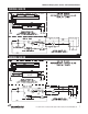
500 Series Display Cases Service and Installation Manual WIRING: 500 CR WIRING: 500 OR NEUTRAL NEUTRAL For customer service, call (800) 733-8829, (800) 773-8821, Fax (989) 773-3210, www.delfield.
500 Series Display Cases Service and Installation Manual WIRING: 500 CD WIRING: 500 CH RED 2 1 L H 1 H 2 2 P L 120V 1 L H 1 H 2 For customer service, call (800) 733-8829, (800) 773-8821, Fax (989) 773-3210, www.delfield.
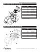
500 Series Display Cases Service and Installation Manual REPLACEMENT PARTS LIST FOR 537-CD KEY QUANTITY DELFIELD PART# DESCRIPTION 1 1 001-3133 mirror, acrylic, RH, 500-CD 2 1 001-3134 mirror, acrylic, LH, 500-CD 3 1 397-8121 holder, adj. shelf, RH 4 1 397-8120 holder, adj. shelf, LH 5 2 001-5285 diffuser, air 537-CD/CR 6 2 XMK00127 fixture, flour.
500 Series Display Cases Service and Installation Manual REPLACEMENT PARTS LIST FOR 561-CD KEY QUANTITY DELFIELD PART# DESCRIPTION 1 1 001-3133 mirror, acrylic, RH, 500-CD 2 1 001-3134 mirror, acrylic, LH, 500-CD 3 1 397-8121 holder, adj. shelf, RH 4 1 397-8120 holder, adj. shelf, LH 5 2 XMK00129 fixture, flour.
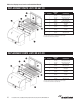
500 Series Display Cases Service and Installation Manual REPLACEMENT PARTS LIST FOR 537CR/CRR 9 11 10 2 4 6 7 3 13 12 6 5 1 14 15 16 KEY QUANTITY DELFIELD PART# DESCRIPTION 1 1 001-3131 mirror, acrylic, RH, 500-CR 2 1 001-3132 mirror, acrylic, LH, 500-CR 3 1 397-8121 holder, adj. shelf, RH 4 1 397-8120 holder, adj. shelf, LH 5 2 001-5285 diffuser, air 537-CD/CR 6 2 XMK00127 fixture, flour.
500 Series Display Cases Service and Installation Manual REPLACEMENT PARTS LIST FOR 561-CR/CRR KEY QUANTITY DELFIELD PART# DESCRIPTION 1 1 001-3133 mirror, acrylic, RH 2 1 001-3132 mirror, acrylic, LH 3 1 397-8121 holder, adj. shelf, RH 4 1 397-8120 holder, adj. shelf, LH 5 2 XMK00129 fixture, flour.
500 Series Display Cases Service and Installation Manual REPLACEMENT PARTS LIST FOR 549-CH 15 KEY DELFIELD PART# 1 323-4055 door set, 49” curved glass 2 345-5439 glass, curved, 1” insulated, 47” 3 219-3959 bulb, 25W, Teflon coated, clear 4 219-3960 lamp holder, twin-threaded 5 219-3970 heater, pad, 115V/90W 6 XMK00106 warmer, food, 208V, no drain 7 219-4212 switch, 30A 120/277V 8 219-0154 switch, rocker, 20A/125V, 15A/250V 1 11 4 3 10 4 3 DESCRIPTION 9 351-6059 thermometer
500 Series Display Cases Service and Installation Manual REPLACEMENT PARTS LIST FOR 573-CH KEY DELFIELD PART# 1 323-4069 door set, 73” curved glass 2 345-5443 glass, curved, 1” insulated, 71” 3 219-3959 bulb, 25W, Teflon coated, clear 4 219-3960 lamp holder, twin-threaded 5 219-3970 heater, pad, 115V/90W 6 XMK00106 warmer, food, 208V, no drain 7 219-4212 switch, 30A 120/277V 8 219-0154 switch, rocker, 20A/125V, 15A/250V 15 1 11 4 3 10 4 3 13 11 5 14 6 2 9 351-6059 therm
500 Series Display Cases Service and Installation Manual FLUORESCENT LIGHT 7 1 8 9 2 7 5 4 6 DELFIELD PART# DESCRIPTION 1 SMK00571 cap, end, top mtg, pigtail, -rem. 2 SMK00572 cap, end, top mtg, blank, -rem. 3 170-1045 diffuser, fluor. light, 24” 170-1046 diffuser, fluor. light, 36” 170-1047 diffuser, fluor. light, 48” 170-1054 diffuser, fluor.
500 Series Display Cases Service and Installation Manual Door Assembly KEY DELFIELD PART# DESCRIPTION 323-7490 complete assembly, 537-CD/CR/CRR 323-4697 complete assembly, 549-CD/CR/CRR 323-4055 complete assembly, 549-CH 323-4698 complete assembly, 561-CD 323-4699 complete assembly, 573-CD 1 323-4636 single roller, 537, 549 & 561 323-4637 double roller, 573 2 order by size bumper gasket, 241/8 & 537 323-3936 bumper gasket, 245/32, 549, 561 & 573 3 order by size wiper gasket, 537 3
500 Series Display Cases Service and Installation Manual COMPRESSOR/COIL ASSEMBLY 537/549/561-CR/CRR KEY DELFIELD PART# DESCRIPTION 1 010-1916 coil pan assembly 2 001-5251 bracket, fan mounting 001-5417 bracket, fan mounting (537-CR) 3 219-3919 switch, toggle, SPST 4 219-3903 ballast, rapid start (549 & 537-CR) 219-3904 ballast, rapid start (561) 5 6 219-3942 control, SPST 219-3927 control, SPST (537-CR) 351-6231 evaporator coil, 404A 351-6072 evaporator coil, 404A (537-CR) 7 2
500 Series Display Cases Service and Installation Manual DELFIELD FOOD WELL (DFW) ASSEMBLY: WITH INFINITE CONTROL For 500-CH Heated Units DELFIELD PART# DESCRIPTION XMK00106 Complete assembly, infinite w/o drain 1 GMK00061 Deflector plate 2 GMK00062 Bottom cover 3 016-0014 Food well, with drain 4 932-1353 Screw 5 219-4007 Element 6 932-1379 Screws (2) 7 343-4663 Insulation 8 219-4335 Thermostat non-adjustable 9 932-1007 Screw 10 GMK00063 Drain cover 11 932-1007 Screws (2
500 Series Display Cases Service and Installation Manual REPLACEMENT PARTS LIST — NOT SHOWN ON EXPLODED VIEWS DELFIELD PART# DESCRIPTION DELFIELD PART# DESCRIPTION CR & CRR MODELS (MISC. PARTS) OR MODELS (MISC. PARTS) Harness, wiring-female, 84” . . . . . . . . . . . . . . . . . . . . . . . . . . . . . . . . . . 218-3596 Motor, evaporator . . . . . . . . . . . . . . . . . . . . . . . . . . . . . . . . . . . . . . . . . . 216-2667 Glass, curved, 1”, insulated, 35” (537) . . . . . . . . . . . . . . .
500 Series Display Cases Service and Installation Manual STANDARD LABOR GUIDELINES TO REPAIR OR REPLACE PARTS ON DELFIELD EQUIPMENT Advice and recommendations given by Delfield Service Technicians do not constitute or guarantee any special coverage. • A maximum of 1-hour is allowed to diagnose a defective component. • A maximum of 1-hour is allowed for retrieval of parts not in stock. • A maximum travel distance of 100 miles round trip and 2-hours will be reimbursed.
500 Series Display Cases Service and Installation Manual STANDARD ONE YEAR WARRANTY (ONE YEAR PARTS, 90 DAYS LABOR.
500 Series Display Cases Service and Installation Manual ADDITIONAL FOUR YEAR PROTECTION PLAN Delfield Model# Serial # Installation Date In addition to the Standard One Year Warranty on the MotorCompressor contained in the above listed Delfield product (the “Unit”), The Delfield Company (“Delfield”) also agrees to repair, or exchange with similar or interchangeable parts in design and capacity at Delfield’s option, the defective Motor-Compressor contained in the Unit (the “Motor-Compressor), or any part
500 Series Display Cases Service and Installation Manual NOTES: For customer service, call (800) 733-8829, (800) 773-8821, Fax (989) 773-3210, www.delfield.
NORTH AMERICA 12 10 1 11 6 4 4 8 5 2 3 14 13 7 9 12 1) The Delfield Company 980 South Isabella Road Mt. Pleasant, MI 48858 800.733.8829 989.773.7981 989.773.3210 FAX custom parts direct from Delfield 5) Contract Ice 2) A.I.S. Commercial Parts & Service 3) Appliance Installation Service 4) Pacific Coast Parts 1816 West 26th Street Erie, PA 16508-1149 800.332.3732 814.456.3732 814.452.4843 FAX 1336 Main Street Buffalo, NY 14209 800.722.1252 716.884.7425 716. 884.