Shelleymatic® by Delfield Dispensing Models Service and Installation Manual Please read this manual completely before attempting to install or operate this equipment! Notify carrier of damage! Inspect all components immediately. See page 2.
Dispensing Models Service and Installation Manual Serial Number Location Contents RECEIVING & INSPECTING EQUIPMENT.................................. 2 SPECIFICATIONS......................................................................3-5 INSTALLATION . ......................................................................... 6 OPERATION..............................................................................7-8 WIRING DIAGRAMS..............................................................
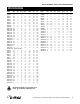
Dispensing Models Service and Installation Manual Specifications MODEL NUMBER LENGTH DEPTH HEIGHT MAXIMUM DISH DIA. VOLTAGE (60Hz/1Ø) AMPS NEMA PLUG Dish Dispensers — Mobile Two Stack MODEL NUMBER LENGTH DEPTH HEIGHT MAXIMUM DISH DIA. VOLTAGE (60Hz/1Ø) AMPS NEMA PLUG Dish Dispensers — Mobile Four Stack CAB2-500 28.25 17 36 5 N/A N/A N/A CAB4-500 27 27 36 5 N/A N/A N/A CAB2-575 28.25 17 36 5.75 N/A N/A N/A CAB4-575 27 27 36 5.
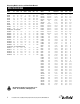
Dispensing Models Service and Installation Manual Specifications MODEL NUMBER FLANGE DIA. HEIGHT CUTOUT DIA. MAXIMUM DISH DIA. VOLTAGE (60Hz/1Ø) AMPS NEMA PLUG MODEL NUMBER CUTOUT SIZE MAXIMUM RACK/TRAY SIZE LENGTH DEPTH HEIGHT Tray/Rack Dispensers Dish Dispensers — Drop-In DIS-500 8.37 28 7.75 5 N/A N/A N/A LT-2020 22.75 X 26 20 X 20 26.75 27.13 27.5 DIS-575 9.12 28 8.5 5.75 N/A N/A N/A LT2-1221 27 X 27.75 10 X 20 31.75 28.13 27.5 DIS-650 9.87 28 9.25 6.
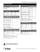
Dispensing Models Service and Installation Manual Specifications MODEL NUMBER FLANGE DIAMETER HEIGHT CUTOUT DIAMETER DISH DIAMETER SHIP WEIGHT 5.12” 2.5”-4.63” — 28” 5.87” X 5.87" 15 MODEL NUMBER L D H CUTOUT DIMENSION MAXIMUM TRAY SIZE CP-2 32.5” 28” 36” 100 1/3 10.0 410 BUILT-IN TRAY AND RACK DISPENSERS TG-1014 21.38” 14” 28” 16.88” X 11.5” TG-1216 18.38” 20” 28” 13.88” X 17.5” TG-1221 18.38” 25” 28” 13.88” X 22.5” TG-1418 20.38” 22” 28” 15.88” X 19.5” TG-1422 26” 20.38” 28” 23.
Dispensing Models Service and Installation Manual Installation: DISH DISPENSERS Location Drop-in units require a counter cutout of a specific size for proper fit. Refer to specification data on page three for the proper dimensions. Heated units must have minimum 1” (2.5cm) air gap between the bottom of the dispensing tube and any surface or objects below. Make sure the tube will have proper clearance when installing it into a counter or another piece of equipment.
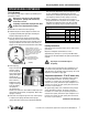
Dispensing Models Service and Installation Manual OPERATION DISH DISPENSERS Field adjustment The dispensing height may be adjusted, by following these instructions in order: Always wear safety glasses when adjusting your dispenser. Springs under tension may recoil when released. WEAR If adjusting a heated model, unplug the unit. Allow the unit to cool completely before handling. DANGER 1) Lock brakes on mobile units before beginning. 2) Unload the dispenser.
Dispensing Models Service and Installation Manual Operation: dish dispensers (continued) The thermostat is located on the bottom of the unit near the fan motor. Use the following directions to adjust. Unplug the unit and allow the unit to cool completely before handling. DANGER 1) Lock brakes on mobile units before beginning. 2) Unload the dispenser. Remove dispensers from the unit by grasping the black plastic guide posts and lifting the dispenser completely out of the unit.
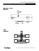
Dispensing Models Service and Installation Manual Wiring diagrams: heated dish dispensers DIS, T-H, & TG-H MODELS CORD & PLUG MOTOR ON/OFF SWITCH HEATER THERMOSTAT LIMIT CAB MODELS DIS DIS DIS DIS CAB MODELS CONTAIN SEVERAL DIS UNITS WIRED TOGETHER For customer service, call (800) 733-8829, (800) 773-8821, Fax (989) 773-3210, www.delfield.
Dispensing Models Service and Installation Manual Wiring diagrams: CP, CM, CMB, CPB MODELS dispensers L1 N ON/OFF SWITCH CONDENSING UNIT BLACK/ ORANGE 2 C1 PRESS SWITCH 4 C1 X PURPLE ORANGE FAN DELAY 3 C1 1 C1 TIMER N WHITE EVAP FANS RED DEFROST HEATER CONDENSATE HEATER 10 For customer service, call (800) 733-8829, (800) 773-8821, Fax (989) 773-3210, www.delfield.
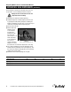
Dispensing Models Service and Installation Manual Maintenance: dish dispensers Unheated dish dispensers Lift the dispenser out of the counter or CAB cart by grasping the black dish guides and lifting straight up and out. Remove any debris that may be in the assembly with a damp cloth. Clean the stainless steel by using a soft cloth, soap and warm water. If this is not sufficient, try ammonia and water or a non-abrasive liquid cleaner. Rub with the grain of the stainless steel to avoid marring the finish.
Dispensing Models Service and Installation Manual Troubleshooting reference chart: heated dish dispensers Problem No Heat Possible Cause Power cord disconnected 1a) GFCI tripped Disconnected ON/OFF switch or ON/OFF switch in the OFF position Defective heating element Air circulating fan defective or blocked Unit plugged into incorrect voltage Not Hot Enough Too Hot Noisy 12 Thermostat set too low Air circulating fan partially blocked Not waiting long enough for pre-heating Solutions Check power sou
Dispensing Models Service and Installation Manual Adjusting self-leveling dispensers Adjusting the self-leveling dispenser Tools Needed: One small flat head screw driver; One Phillips head screw driver 1. Always wear safety glasses when adjusting your dispenser. Also, lock brakes on mobile units before beginning. 2. Unload dispenser and remove stainless steel load tray by lifting straight up and set it aside (see fig. 1). For Models LT skip to step #6. 5.
Dispensing Models Service and Installation Manual REPLACEMENT PARTS LIST Models T, T2 1014 units 0201735 6150201 6230170 6320257 M3234180 M3234185 Elevator assembly, small Spring, extension, 0.58lbs/in Bumper, corner, small pvc Bearing, elev, o.375ID Polyolefin caster 4” with brake Polyolefin caster 4” without brake 1216/1222/1418/ 1422/1520/ 1622/1826/2020 units 0201709 6150202 6230170 6320257 M3234180 M3234185 Elevator assembly, large Spring, extension, 0.
Dispensing Models Service and Installation Manual REPLACEMENT PARTS LIST 913 units 6200126 6970016 1013 units 6200127 6970017 1200 units 6200128 6970018 1450 units 6200129 6970026 Spinning head Wire head Spinning head Wire head Spinning head Wire head 6230314 6230244 6150201 6150202 6150203 6190085 6160024 6190180 2190154 6190181 Filter, air, 6” diameter Guide post Spring, heavy tension Spring, medium tension Spring, light tension Cord with plug, NEMA 5-15P 5’ Motor, 115V 50-60Hz Switch, high-limit,
Dispensing Models Service and Installation Manual REPLACEMENT PARTS LIST CT/WCT-1622 0047496 Carrier 16.56 x 22.56 CT-1821 and WCT-2020 0047499 Carrier 20.56 x 21.56 CT/WCT-1826 0047498 Carrier 18.56 x 26.56 Model FT2-SN All units 6230170 6230218 0201734 6320007 6150201 6150202 6230024 0680934 6150203 0047241 0047239 3234052 Corner bumper 4” caster Large elevator Bearing Extension spring .58 Extension spring .28 Retainer ND-napkin dispenser Extension spring .
Dispensing Models Service and Installation Manual Standard Labor Guidelines To Repair or Replace Parts on Delfield Equipment Advice and recommendations given by Delfield Service Technicians do not constitute or guarantee any special coverage. • A maximum of 1-hour is allowed to diagnose a defective component. • A maximum of 1-hour is allowed for retrieval of parts not in stock. • A maximum travel distance of 100 miles round trip and 2-hours will be reimbursed.
Dispensing Models Service and Installation Manual Standard One Year Warranty (One year parts, 90 days labor.
Dispensing Models Service and Installation Manual Additional Four Year Protection Plan Delfield Model# Serial # Installation Date In addition to the Standard One Year Warranty on the MotorCompressor contained in the above listed Delfield product (the “Unit”), The Delfield Company (“Delfield”) also agrees to repair, or exchange with similar or interchangeable parts in design and capacity at Delfield’s option, the defective Motor-Compressor contained in the Unit (the “Motor-Compressor), or any part ther
Delfield ™ Mt. Pleasant, MI ® Covington, TN Thank you for choosing Delfield! Help is a phone call away. Help our team of professional, courteous customer service reps by having your model number and serial number available at the time of your call (800) 733-8829. Model:_____________________ S/N: ____________________ Installation Date:_____________ For a list of Delfield’s authorized parts depots, visit our website at www.delfield.com. Delfield ™ ® 980 S. Isabella Rd., Mt. Pleasant, MI 48858, U.S.A.