
Installation manual


Dispensing Models Service and Installation Manual
For customer service, call (800) 733-8829, (800) 773-8821, Fax (989) 773-3210, www.delfield.com
6
Location
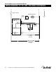
Drop-in units require a counter cutout of a specific size
for proper fit. Refer to specification data on page three for
the proper dimensions.
Heated units must have minimum 1” (2.5cm) air
gap between the bottom of the dispensing tube and
any surface or objects below. Make sure the tube
will have proper clearance when installing it into a
counter or another piece of equipment.
Stabilizing
CAB models are supplied with casters for your convenience,
for ease of cleaning underneath and mobility.
The unit must be installed in a stable condition
with the front wheels locked. Locking the front
casters after installation is the owner’s and
operator’s responsibility.
Electrical Connection
All heated DIS and CAB models are tested at the factory to
assure proper operation.
Refer to the amperage data on page three, the serial tag, your
local or the National Electrical Code to be sure the unit is
connected to the proper power source. A protected circuit of
the correct voltage and amperage must run for connection of
the line cord.
DIS models plug into a wall receptacle when used as drop-in
models; if they are grouped together in a CAB model, all of the
individual DIS power cords are plugged into the receptacle in
the CAB cabinet. The master power cord on CAB models plugs
into a wall receptacle.
The unit must be disconnected from the
power source whenever performing service or
maintenance functions.
DA RNGE
INSTALLATION: DISH DISPENSERS
INSTALLATION: MOBILE AND BUILT-IN CHILLED PLATE AND MUG DISPENSERS
INSTALLATION: NAPKIN/CUP DISPENSERS
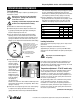
Location
For built-in models (CPB & CMB) be sure the location
chosen has a floor strong enough to support the total
weight of the cabinet and contents. Units in this product
line can weigh as much as 1500 pounds when fully
loaded. Reinforce the floor as necessary to provide for
maximum loading.
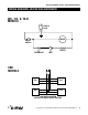
Cutout dimensions for CPB-2 and CPB-4 are 13.25” x 23/
25”; two cutouts, 2.125” apart are required on the CPB-4.
Cutout dimensions for the CMB-2 are 25.25” x 22.25”
For the most efficient refrigeration, be sure to provide
good air circulation inside and out. On the CP and CM
mobile units, allow 3.50” clearance for air circulation.
For built in units be sure there is ample air flow from front and
rear of unit with ventilation openings equivalent to one square
foot of opening.
Refer to the amperage data on page three, the
serial tag, your local or the National Electrical Code
to be sure the unit is connected to the proper power
source. A protected circuit of the correct voltage and
amperage must run for connection of the line cord.
The unit must be disconnected from the
power source whenever performing service or
maintenance functions.
DA RNGE
DA RNGE
Napkin and cup units require a counter cutout of a specific
size for proper fit. Refer to specification data on page three
for the proper dimensions.