
Installation and Service Manual

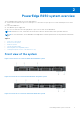
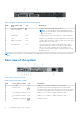
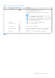
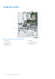
Table Of Contents
- Dell EMC PowerEdge R250 Installation and Service Manual
- Contents
- About this document
- PowerEdge R250 system overview
- Initial system setup and configuration
- Minimum to POST and system management configuration validation
- Installing and removing system components
- Safety instructions
- Before working inside your system
- After working inside your system
- Recommended tools
- Optional front bezel
- System cover
- Optional optical drive
- Air shroud
- Cooling fans
- Intrusion switch
- Drive backplane
- Drives
- Cable routing
- System memory
- Processor and heat sink
- Expansion cards and expansion card risers
- Optional IDSDM module
- MicroSD card
- Optional BOSS S1 card
- PERC
- System battery
- Optional internal USB card
- Power supply unit
- System board
- Trusted Platform Module
- Control panel
- Jumpers and connectors
- System diagnostics and indicator codes
- Getting help
- Documentation resources

Table 2. Rear view of the system (continued)
Item Ports, panels, or slots Icon Description
6 System ID button Press the system ID button:
● To locate a particular system within a rack.
● To turn the system ID on or off.
To reset iDRAC, press and hold the button for more than 16
seconds.
NOTE:
● To reset iDRAC using system ID, ensure that the system ID
button is enabled in the iDRAC setup.
● If the system stops responding during POST, press and hold
the system ID button (for more than 5 seconds) to enter
the BIOS progress mode. LED.
7 CMA jack N/a Enables you to connect to cable management arm
8 USB 3.2 Gen 1 port This port is USB 3.0-compliant.
9 USB 2.0 port This port is USB 2.0-compliant.
10 iDRAC ethernet port Enables you to remotely access iDRAC. For more information, see
the iDRAC User's Guide at www.dell.com/poweredgemanuals
11 VGA port Enables you to connect a display device to the system.
NOTE: For more information, see the Dell EMC PowerEdge R250 Technical Specifications on the product documentation
page.
PowerEdge R250 system overview 9