User’s Manual NetXtreme-E Broadcom® NetXreme-C and NetXtreme-E USER’S MANUAL NetXtreme-E-UG103 September 5, 2019
Revision History Revision Date Change Description NetXtreme-E-UG102 9/5/19 Updated: 4/24/19 • “Network Link and Activity Indication” on page 16 • “Configuring the VM on Linux Guest OS” on page 78 • Added OCP 3.0 card suport. Updated: 4/1/19 2/26/18 • “BCM957414M4140D” on page 21 • “Configuring the VM on Linux Guest OS” on page 80 Minor updates. Initial release for 20.6. NetXtreme-E-UG102 NetXtreme-E-UG101 NetXtreme-E-UG100 © 2019 by Broadcom. All rights reserved.
NetXtreme-E User’s Manual Table of Contents Table of Contents Regulatory and Safety Approvals ............................................................................................................... 7 Regulatory ............................................................................................................................................... 7 Safety ..........................................................................................................................................
NetXtreme-E User’s Manual Table of Contents NPAR, SR-IOV, and RoCE ............................................................................................................ 30 NPAR, SR-IOV, and DPDK............................................................................................................ 30 Unsupported Combinations............................................................................................................ 30 Installing the Hardware .....................................
NetXtreme-E User’s Manual Table of Contents Firmware Image Properties............................................................................................................ 43 Device Level Configuration ............................................................................................................ 43 NIC Configuration........................................................................................................................... 43 iSCSI Configuration...........................
NetXtreme-E User’s Manual Table of Contents Linux Use Case ..................................................................................................................................... 63 Windows Case ...................................................................................................................................... 64 VMWare SRIOV Case...........................................................................................................................
NetXtreme-E User’s Manual Regulatory and Safety Approvals Regulatory and Safety Approvals The following sections detail the Regulatory, Safety, Electromagnetic Compatibility (EMC), and Electrostatic Discharge (ESD) standard compliance for the NetXtreme-E Network Interface Card. Regulatory Table 1: Regulatory Approvals Item Applicable Standard Approval/Certificate CE/European Union EN 62368-1:2014 CB report and certificate UL/USA IEC 62368-1 ed. 2 CB report and certificate CSA/Canada CSA 22.
NetXtreme-E User’s Manual Regulatory and Safety Approvals Electromagnetic Compatibility (EMC) Table 3: Electromagnetic Compatibility Standard / Country Certification Type Compliance CE/EU EN 55032:2012/AC:2013 Class B EN 55024:2010 EN 61000-3-2:2014 EN 61000-3-3:2013 CE report and CE DoC FCC/USA CFR47, Part 15 Class B FCC/IC DoC and EMC report referencing FCC and IC standards IC/Canada ICES-003 Class B FCC/IC DoC and report referencing FCC and IC standards ACA/Australia, New Zealand AS/NZS CI
NetXtreme-E User’s Manual Functional Description Functional Description Dell supports 1GBase-T, 10GBase-T, 10G SFP+, and 25G SFP28 Network Interface Cards (NICs). These NICs are described in Table 5.
NetXtreme-E User’s Manual Functional Description Figure 1: BCM957402A4020DC, BCM957412A4120D Network Interface Card September 4, 2019 • NetXtreme-E-UG103 Page 10
NetXtreme-E User’s Manual Functional Description Figure 2: BCM957404A4041DLPC, BCM957414A4141D Network Interface Card September 4, 2019 • NetXtreme-E-UG103 Page 11
NetXtreme-E User’s Manual Functional Description Figure 3: BCM957406A4060DLPC, BCM957416A4160D Network Interface Card Figure 4: BCM957414M4140D Network Daughter Card (rNDC) September 4, 2019 • NetXtreme-E-UG103 Page 12
NetXtreme-E User’s Manual Functional Description Figure 5: BCM957412M4120D Network Daughter Card (rNDC) Figure 6: BCM957416M4160 Network Daughter Card (rNDC) September 4, 2019 • NetXtreme-E-UG103 Page 13
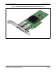
NetXtreme-E User’s Manual Functional Description Figure 7: BCM957412N4120 Small-Form-Factor Network Adapter Figure 8: BCM957414N4140 Small-Form-Factor Network Adapter September 4, 2019 • NetXtreme-E-UG103 Page 14
NetXtreme-E User’s Manual Functional Description Figure 9: BCM957416N4160 Small-Form-Factor Network Adapter September 4, 2019 • NetXtreme-E-UG103 Page 15
NetXtreme-E User’s Manual Network Link and Activity Indication Network Link and Activity Indication BCM957402AXXXX/BCM957412AXXXX The SFP+ port has two LEDs to indicate traffic activities and link speed. The LEDs are shown in Figure 10 and described Table 6.
NetXtreme-E User’s Manual Network Link and Activity Indication BCM957404AXXXX/BCM957414AXXXX The SFP28 port has two LEDs to indicate traffic activities and link speed. The LEDs are shown in Figure 11 and described Table 7.
NetXtreme-E User’s Manual Network Link and Activity Indication BCM957406AXXXX/BCM957416AXXXX Each Ethernet interface has a link LED to indicate Link status and an activity LED to indicate data traffic. The LEDs are shown in Figure 12 and described Table 8.
NetXtreme-E User’s Manual Network Link and Activity Indication BCM957414M4140D The SFP28 port has two LEDs to indicate traffic activities and link speed. The LEDs are shown in Figure 13 and described Table 9.
NetXtreme-E User’s Manual Network Link and Activity Indication BCM957412M4120D This rNDC has SFP+ and RJ-45 ports, each with two LEDs to indicate traffic activities and link speed. The LEDs are shown in Figure 14 and described Table 10 (Ports 1 and 2)/Table 11 (Ports 3 and 4).
NetXtreme-E User’s Manual Network Link and Activity Indication BCM957416M4160 This rNDC has 10GBaseT and 1000BaseT RJ-45 ports, each with two LEDs to indicate traffic activities and link speed. The LEDs are shown in Figure 16 and described Table 12.
NetXtreme-E User’s Manual Network Link and Activity Indication BCM957412N4120DC The SFP+ port supports two LEDs to indicate traffic activities and link speed. The LEDs are shown in Figure 16 and described Table 13. Its locations and form factors conform to the OCP 3.0 Design Specification.
NetXtreme-E User’s Manual Network Link and Activity Indication BCM957414N4140DC The SFP+ port supports two LEDs to indicate traffic activities and link speed. The LEDs are shown in Figure 17 and described Table 14. Its locations and form factors conform to the OCP 3.0 Design Specification.
NetXtreme-E User’s Manual Network Link and Activity Indication BCM957416N4160DC Each Ethernet interface has a link LED to indicate Link status and an activity LED to indicate data traffic. The LEDs are shown in Figure 18 and described Table 15. Its locations and form factors conform to the OCP 3.0 Design Specification.
NetXtreme-E User’s Manual Features Features Refer to the following sections for device features. Software and Hardware Features Table 16 provides a list of host interface features. Table 16: Host Interface Features Feature Details Host Interface PCI-E v3.0 (Gen 3: 8 GT/s; Gen 2: 5 GT/s; Gen 1: 2.5 GT/s). Number of PCI-E lanes PCI-E edge connector: x8. Vital Product Data (VPD) Supported. Alternate Routing ID (ARI) Supported. Function Level Reset (FLR) Supported.
NetXtreme-E User’s Manual Features Table 16: Host Interface Features (Cont.) Feature Details Jumbo Frames Supported. iSCSI boot Supported. NIC Partitioning (NPAR) Supports up to eight Physical Functions (PFs) per port, or up to 16 PFs per silicon. This option is configurable in NVRAM. RDMA over Converged Ethernet (RoCE) The BCM5741X supports RoCE v1/v2 for Windows, Linux, and VMware. Data Center Bridging (DCB) The BCM5741X supports DCBX (IEEE and CEE specification), PFC, and AVB.
NetXtreme-E User’s Manual Features VXLAN A Virtual eXtensible Local Area Network (VXLAN), defined in IETF RFC 7348, is used to address the need for overlay networks within virtualized data centers accommodating multiple tenants. VXLAN is a Layer 2 overlay or tunneling scheme over a Layer 3 network. Only VMs within the same VXLAN segment can communicate with each other. NVGRE/GRE/IP-in-IP/Geneve Network Virtualization using GRE (NVGRE), defined in IETF RFC 7637, is similar to a VXLAN.
NetXtreme-E User’s Manual Features Stateless Transport Tunnel Offload Stateless Transport Tunnel Offload (STT) is a tunnel encapsulation that enables overlay networks in virtualized data centers. STT uses IP-based encapsulation with a TCP-like header. There is no TCP connection state associated with the tunnel and that is why STT is stateless. Open Virtual Switch (OVS) uses STT. An STT frame contains the STT frame header and payload. The payload of the STT frame is an untagged Ethernet frame.
NetXtreme-E User’s Manual Features SR-IOV The PCI-SIG defines optional support for Single-Root IO Virtualization (SR-IOV). SR-IOV is designed to allow access of the VM directly to the device using Virtual Functions (VFs). The NIC Physical Function (PF) is divided into multiple virtual functions and each VF is presented as a PF to VMs. SR-IOV uses IOMMU functionality to translate PCI-E virtual addresses to physical addresses by using a translation table.
NetXtreme-E User’s Manual Features Supported Combinations The following sections describe the supported feature combinations for this device. NPAR, SR-IOV, and RoCE Table 18 provides the supported feature combinations of NPAR, SR-IOV, and RoCE.
NetXtreme-E User’s Manual Installing the Hardware Installing the Hardware Safety Precautions Caution! The adapter is being installed in a system that operates with voltages that can be lethal. Before removing the cover of the system, observe the following precautions to protect yourself and to prevent damage to the system components: • • • • Remove any metallic objects or jewelry from your hands and wrists. Make sure to use only insulated or nonconducting tools.
NetXtreme-E User’s Manual Installing the Hardware Installing the Adapter The following instructions apply to installing the Broadcom NetXtreme-E Ethernet adapter (add-in NIC) into most servers. Refer to the manuals that are supplied with the server for details about performing these tasks on this particular server. 1. Review the “Safety Precautions” on page 31 and “Preinstallation Checklist” before installing the adapter.
NetXtreme-E User’s Manual Installing the Hardware Table 20: Supported Cables and Modules (Cont.) Optical Module Dell Part Number Adapters Description FTLX8574D3BCL-FC WTRD1 or PLRXPLSCS43811 BCM57402X, BCM57404X, 10 Gbps-SR SFP+ Transceiver BCM57412X, BCM57414X SFP+ to 1000BASET XTY28 Tranceiver BCM57412X, BCM57414X SFP+ to 1000BASET Tranceiver SFP+ to 10GBASET Tranceiver BCM57412X, BCM57414X SFP+ to 10GBASET Tranceiver PGYJT Note: 1.
NetXtreme-E User’s Manual Software Packages and Installation Software Packages and Installation Refer to the following sections for information on software packages and installation. Supported Operating Systems Table 21 provides a list of supported operating systems. Table 21: Supported Operating System List OS Flavor Distribution Windows Windows 2012 R2, 2016, or 2019 Linux Redhat RHEL 6.10, RHEL 7.5, RHEL 7.6, RHEL 8.0 SLES 15 SP1 VMWare ESXi 6.5 U3 or 6.
NetXtreme-E User’s Manual Software Packages and Installation Once the files are extracted, INF installation is executed through "upgrade driver" functionality using the Device Manager (devmgmt.msc). Open the Device Manager, select the desired NIC, right click and select the upgrade driver to update it. Linux The Linux drivers are supplied in RPM, KMP, and source code format. To build the device driver from the source code using Linux, refer to the following example: 1.
NetXtreme-E User’s Manual Software Packages and Installation Linux Ethtool Commands Note: In Table 22, ethX should be replaced with the actual interface name. Table 22: Linux Ethtool Commands Command Description ethtool -s ethX speed 25000 autoneg off Set the speed. If the link is up on one port, the driver will not allow the other port to be set to an incompatible speed. ethtool -i ethX Output includes Package version, NIC BIOS version (boot code). ethtool -k ethX Show offload features.
NetXtreme-E User’s Manual Software Packages and Installation Table 22: Linux Ethtool Commands (Cont.) Command Description ip link set ethX vf 0 mac 00:12:34:56:78:9a Set VF MAC address. ip link set ethX vf 0 state enable Set VF link state for VF 0. ip link set ethX vf 0 vlan 100 Set VF 0 with VLAN ID 100. VMware The ESX drivers are provided in VMware standard VIB format. 1.
NetXtreme-E User’s Manual Software Packages and Installation Firmware Update The NIC firmware can be updated using one of the following methods: • Using the Dell Update Package (DUP) when the system is in the OS booted state. This method only applies to the Windows and Linux operating systems. • Using the Dell iDRAC – Lifecycle Controller. This method can be used regardless of the operating system. If the system is running VMware, use the Lifecycle Controller to upgrade the firmware.
NetXtreme-E User’s Manual Windows Driver Advanced Properties and Event Log Messages Windows Driver Advanced Properties and Event Log Messages Driver Advanced Properties The Windows driver advanced properties are shown in Table 24. . Table 24: Windows Driver Advanced Properties Driver Key Parameters Description Encapsulated Task offload Enable or Disable Used for configuring NVGRE encapsulated task offload.
NetXtreme-E User’s Manual Windows Driver Advanced Properties and Event Log Messages Table 24: Windows Driver Advanced Properties (Cont.) Driver Key Parameters Description SR-IOV Enable or Disable. Default Enabled. This parameter works in conjunction with HW configured SR-IOV and BIOS configured SR-IOV setting. TCP/UDP checksum offload IPV4 TX/RX enabled, TX enabled or RX Default RX and TX enabled. Enabled or offload disabled.
NetXtreme-E User’s Manual Windows Driver Advanced Properties and Event Log Messages Table 26: Event Log Messages (Cont.) 0x001A Incompatible speed selection between Port 1 and Port 2. Reported link speeds are correct and might not match Speed and Duplex setting. 0x001B Incompatible speed selection between Port 1 and Port 2. Link configuration became illegal. 0x001C Network controller configured for 25Gb full-duplex link. 0x0020 RDMA support initialization failed.
NetXtreme-E User’s Manual Teaming Teaming Windows The Broadcom NetXtreme-E devices installed on Dell platforms can participate in NIC teaming functionality using the Microsoft teaming solution. Microsoft LBFO is a native teaming driver that can be used in the Windows OS. The teaming driver also provides VLAN tagging capabilities. Linux Linux bonding is used for teaming under Linux. The concept is loading the bonding driver and adding team members to the bond which would load-balance the traffic.
NetXtreme-E User’s Manual System-level Configuration System-level Configuration Refer to the following sections for information on system-level NIC configuration. UEFI HII Menu Broadcom NetXtreme-E series controllers can be configured for preboot, iSCSI and advanced configuration such as SR-IOV using HII (Human Interface) menu. To configure the settings, during system boot select F2 -> System Setup -> Device Settings. Select the desired network adapter for viewing and changing the configuration.
NetXtreme-E User’s Manual System-level Configuration Refer to “ISCSI Boot” on page 54 for detailed configuration information. Comprehensive Configuration Management Preboot configuration can be configured using the Comprehensive Configuration Management (CCM) menu option. During the system BIOS POST, the Broadcom banner message will be displayed with an option to change the parameters through the Control-S menu.
NetXtreme-E User’s Manual System-level Configuration Auto-Negotiation Configuration Note: In NPAR (NIC partitioning) devices where one port is shared by multiple PCI functions, the port speed is preconfigured and cannot be changed by the driver.
System-level Configuration NetXtreme-E User’s Manual Table 27: Supported Combination of Link Speed Settings Port 2 Link Setting Port1 Link Speed Setting Forced 1G Forced 10G Forced 25G Forced 1G Forced 10G AN Enabled {1/ 25G} AN Enabled {10/ 25G} AN Enabled {1/10/ 25G} P1: no AN P1: no AN P1: no AN P1: no AN P1: no AN P1: no AN P1: no AN P1: no AN P1: no AN P2: no AN P2: {1G} P2: AN {10G} P2: AN {25G} P2: AN {1/10G} P2: AN {1/25G} P2: AN {10/25G} P2: AN {1/10/25G} Not supported Not
System-level Configuration NetXtreme-E User’s Manual • {link speed} – expected link speed • AN {link speeds} – advertised supported auto-negotiation link speeds. The expected link speeds based on the local and link partner settings are shown in Table 28.
NetXtreme-E User’s Manual System-level Configuration Firmware Link Speed This option configures the link speed used by the firmware when the device is in D3. Auto-negotiation Protocol This is the supported auto-negotiation protocol used to negotiate the link speed with the link partner. This option must match the AN protocol setting in the link partner port. The Broadcom NetXtreme-E NIC supports the following auto-negotiation protocols: IEEE 802.3by, 25G/50G consortiums and 25G/50G BAM.
NetXtreme-E User’s Manual System-level Configuration ethtool -A eth0 autoneg on|off Use this command to enable/disable Pause frame auto-negotiation. ethtool -a eth0 Use this command to display the current flow control auto-negotiation setting. ESXi Driver Settings Note: For 10GBase-T NetXtreme-E network adapters, auto-negotiation must be enabled. Using forced speed on 10GBase-T adapter results in esxcli command failure. Note: VMWare does not support 25G speeds in ESX6.0.
NetXtreme-E User’s Manual System-level Configuration FEC Auto-Negotiation To enable/disable Link FEC auto-negotiation, the following options can be enabled in the system BIOS HII menu or in CCM: • System BIOS->Device Settings->NetXtreme-E NIC->Device Level Configuration The FEC Auto-negotiation uses two parameters during negotiation exchange: FEC capable and FEC request. If the NIC advertises it as FEC Auto-negotiation capable, then the FEC settings are driven by the Switch.
NetXtreme-E User’s Manual System-level Configuration Table 30: Supported FEC Configurations for the BCM5741X Link Partner FEC Setting Local FEC Setting Force Speed No FEC Force Speed Base-R FEC CL74 Force Speed RS-FEC CL91/ CL108 AN (None) An (None, Base- AN (None, Base-R, R) RS) Force No FEC Link w/no FEC No link No link No link No link No link Force Speed Base-R FEC CL74 No link Base-R FEC CL74 No link No link No link No link Force RSFEC CL91/ CL108 No link No link RS-FEC CL91/ CL
NetXtreme-E User’s Manual System-level Configuration Table 31: Link Training Relationship Between Media Type and Speed Link Partner Link Training Setting Local and Media Cable Type Force Speed Link Training Disabled Force Speed Link Training Enabled AN (Auto-Link Training) Force Speed DAC (SFP+/SFP28/ QSFP28) Link without Link Training Link with Link Training Link with Link Training Force Speed optical (Transceiver/AOC) Link without Link Training Link without Link Training N/A AN DAC (SFP+SFP28
NetXtreme-E User’s Manual System-level Configuration Table 32 and Table 33 show the link results with the Media Auto Detect feature enabled.
NetXtreme-E User’s Manual ISCSI Boot ISCSI Boot Broadcom NetXtreme-E Ethernet adapters support iSCSI boot to enable the network boot of operating systems to diskless systems. iSCSI boot allows a Windows, Linux, or VMware operating system to boot from an iSCSI target machine located remotely over a standard IP network.
NetXtreme-E User’s Manual ISCSI Boot • Target TCP port number • Target LUN • Initiator IQN • CHAP ID and secret Configuring iSCSI Boot Parameters Configure the Broadcom iSCSI boot software for either static or dynamic configuration. Refer toTable 35 for configuration options available from the General Parameters menu. Table 35 lists parameters for both IPv4 and IPv6. Parameters specific to either IPv4 or IPv6 are noted.
NetXtreme-E User’s Manual ISCSI Boot MBA Boot Protocol Configuration To configure the boot protocol: 1. Restart the system. 2. From the PXE banner, select CTRL+S. The MBA Configuration Menu displays. 3. From the MBA Configuration Menu, use the UP ARROW or DOWN ARROW to move to the Boot Protocol option. Use the LEFT ARROW or RIGHT ARROW to change the Boot Protocol option for iSCSI. 4. Select iSCSI Boot Configuration from Main Menu.
NetXtreme-E User’s Manual ISCSI Boot • Secondary DNS • iSCSI Name (corresponds to the iSCSI initiator name to be used by the client system) Note: Enter the IP address. There is no error-checking performed against the IP address to check for duplicates or incorrect segment/network assignment. 5. Select ESC to return to the Main menu. 6. From the Main menu, select 1st Target Parameters. Note: For the initial setup, configuring a second target is not supported. 7.
NetXtreme-E User’s Manual • ISCSI Boot If DHCP Option 17 is used, the target information is provided by the DHCP server, and the initiator iSCSI name is retrieved from the value programmed from the Initiator Parameters screen. If no value was selected, then the controller defaults to the name: iqn.1995-05.com.broadcom.<11.22.33.44.55.66>.iscsiboot where the string 11.22.33.44.55.66 corresponds to the controller's MAC address.
NetXtreme-E User’s Manual ISCSI Boot 5. From the 1st Target Parameters screen, type values for the following using the values used when configuring the iSCSI target: • CHAP ID (optional if two-way CHAP) • CHAP Secret (optional if two-way CHAP, and must be 12 characters in length or longer) 6. Select ESC to return to the Main menu. 7. Select ESC and select Exit and Save Configuration.
NetXtreme-E User’s Manual ISCSI Boot Configuring the DHCP Server to Support iSCSI Boot The DHCP server is an optional component and it is only necessary for dynamic iSCSI Boot configuration setup (see “Dynamic iSCSI Boot Configuration” on page 57). Configuring the DHCP server to support iSCSI boot is different for IPv4 and IPv6. Refer to the following sections: DHCP iSCSI Boot Configurations for IPv4 The DHCP protocol includes a number of options that provide configuration information to the DHCP client.
NetXtreme-E User’s Manual ISCSI Boot Table 37: DHCP Option 43 Suboption Definition Suboption Definition 201 First iSCSI target information in the standard root path format iscsi:"":"":"":"":" 203 iSCSI initiator IQN Using DHCP option 43 requires more configuration than DHCP option 17, but it provides a richer environment and provides more configuration options.
NetXtreme-E User’s Manual VXLAN: Configuration and Use Case Examples Table 38: DHCP Option 17 Suboption Definition Suboption Definition 201 First iSCSI target information in the standard root path format "iscsi:"[]":"":"": "":"" 203 iSCSI initiator IQN Note: In Table 38, the brackets [ ] are required for the IPv6 addresses. The content of option 17 should be <2-byte Option Number 201|202|203> <2-byte length> .
NetXtreme-E User’s Manual SR-IOV: Configuration and Use Case Examples Table 40: VXLAN Command and Configuration Examples System 1 System 2 PxPy: ifconfig PxPy 1.1.1.4/24 PxPy: ifconfig PxPy 1.1.1.2/24 ip link add vxlan10 type vxlan id 10 group 239.0.0.10 dev PxPy dstport 4789 ip link add vxlan10 type vxlan id 10 group 239.0.0.10 dev PxPy dstport 4789 ip addr add 192.168.1.5/24 broadcast 192.168.1.255 dev vxlan10 ip addr add 192.168.1.10/24 broadcast 192.168.1.
NetXtreme-E User’s Manual SR-IOV: Configuration and Use Case Examples Note: Use netxtreme-bnxt_en.tar.gz to install both bnxt_re and bnxt_en for RDMA functionality on SRIOV VFs. 6. Enable Virtual Functions through Kernel parameters: a. Once the driver is installed, lspci will display the NetXtreme-E NICs present in the system. Bus, device, and Function are needed for activating Virtual functions. b. To activate Virtual functions, enter the command shown below: echo X >/sys/bus/pci/device/0000\:Bu
NetXtreme-E User’s Manual SR-IOV: Configuration and Use Case Examples c. Set the number of virtual functions per physical function. d. Set the number of MSI-X vectors per the VF and Max number of physical function MSI-X vectors. If the VF is running out of resources, balance the number of MSI-X vectors per VM using CCM. 2. Enable virtualization in the BIOS: a. During system boot, enter the system BIOS -> Processor settings -> Virtualization Technologies and set it to Enabled. b.
NetXtreme-E User’s Manual SR-IOV: Configuration and Use Case Examples b. During system boot, enter the system BIOS -> Integrated Devices -> SR-IOV Global and set it to Enabled. 3. On ESXi, install the Bnxtnet driver using the following steps: a. Copy the -.vib file in /var/log/vmware. $ cd /var/log/vmware. $ esxcli software vib install --no-sig-check -v -.vib. b. Reboot the machine. c.
NetXtreme-E User’s Manual SR-IOV: Configuration and Use Case Examples esxcli network sriovnic list To enable one or more VFs, the driver uses the module parameter "max_vfs" to enable the desired number of VFs for PFs. For example, to enable four VFs on PF1: esxcfg-module -s 'max_vfs=4' bnxtnet (reboot required) To enable VFs on a set of PFs, use the command format shown below.
NetXtreme-E User’s Manual NPAR – Configuration and Use Case Example NPAR – Configuration and Use Case Example Features and Requirements • OS/BIOS Agnostic – The partitions are presented to the operating system as "real" network interfaces so no special BIOS or OS support is required like SR-IOV. • Additional NICs without requiring additional switch ports, cabling, PCI-E expansion slots.
NetXtreme-E User’s Manual NPAR – Configuration and Use Case Example NPAR is enabled in combination with SR-IOV. For some ARI capable OEM systems, the NParEP button is available to explicitly allow the BCM5741X to support up to 16 partitions. Switching from Single Function mode to Multifunction mode, the device needs to be re-enumerated, therefore changes will not take effect until a system reboot occurs. 2.
NetXtreme-E User’s Manual NPAR – Configuration and Use Case Example 4. Set the NIC Partition Configuration parameters (see Table 41 on page 70). Table 41: NPAR Parameters Parameter Description Valid Options BW Reservation Percentage of total available bandwidth that should be reserved for Value 0-100 this partition. 0 indicates equal division of bandwidth between all partitions. BW Limit Maximum percentage of available bandwidth this partition is allowed.
NetXtreme-E User’s Manual NPAR – Configuration and Use Case Example Notes on Reducing NIC Memory Consumption Because of the faster link speeds supported in this NIC, the default number of receive buffers is larger. More packets can arrive within a given time interval when the link speed is higher, and if the host system is delayed in processing the receive interrupts, the NIC must drop packets if all available receive buffers are in use.
NetXtreme-E User’s Manual RoCE – Configuration and Use Case Examples RoCE – Configuration and Use Case Examples This section provides configuration and use case examples for RoCE. To enable RoCE for PFs or VFs, the user must enable the RDMA selection in the HII menu in the BIOS before the RDMA option takes effect in the host or guest OS. To enable RDMA in single function mode (if Virtualization Mode is None or SR-IOV): 1.
NetXtreme-E User’s Manual RoCE – Configuration and Use Case Examples To compile bnxt_re: $make • Distros that need external OFED to be installed: SLES11SP4 Please refer OFED release notes from the following link and install OFED before compiling bnxt_re driver. http://downloads.openfabrics.org/downloads/OFED/release_notes/OFED_3.18-2_release_notes To compile bnxt_re: $export OFED_VERSION=OFED-3.18-2 $make Installation To install RoCE in Linux: 1.
NetXtreme-E User’s Manual RoCE – Configuration and Use Case Examples Windows Kernel Mode Windows Server 2012 R12 and beyond invokes the RDMA capability in the NIC for SMB file traffic if both ends are enabled for RDMA. Broadcom NDIS miniport bnxtnd.sys v20.6.2 and beyond support RoCEv1 and RoCEv2 via the NDKPI interface. The default setting is RoCEv1. To enable RDMA: 1. Upgrade the NIC NVRAM using the appropriate board packages. In CCM or in UEFI HII, enable support for RDMA. 2.
NetXtreme-E User’s Manual RoCE – Configuration and Use Case Examples Note: By default, the driver sets up two RDMA connections for each network share per IP address (on a unique subnet). The user can scale up the number of RDMA connections by adding multiple IP addresses, each with different a subnet, for the same physical port under test. Multiple network shares can be created and mapped to each link partner using the unique IP addresses created.
NetXtreme-E User’s Manual RoCE – Configuration and Use Case Examples VMware ESX Limitations The current version of the RoCE supported driver requires ESXi-6.5.0 GA build 4564106 or above. BNXT RoCE Driver Requirements The BNXTNET L2 driver must be installed with the disable_roce=0 module parameter before installing the driver. To set the module parameter, run the following command: esxcfg-module -s "disable_roce=0" bnxtnet Please use the ESX6.5 L2 driver version 20.6.9.
NetXtreme-E User’s Manual RoCE – Configuration and Use Case Examples Configuring Paravirtualized RDMA Network Adapters Refer to Vmware.com for additional information on setting up and using Paravirtualized RDMA (PVRDMA) network adapters. Configuring a Virtual Center for PVRDMA To configure a Virtual Center for PVRDMA: 1. Create DVS (requires a Distributed Virtual Switch for PVRDMA) 2. Add the host to the DVS. Tagging vmknic for PVRDMA on ESX Hosts To tag a vmknic for PVRDMA to use on ESX hosts: 1.
NetXtreme-E User’s Manual RoCE – Configuration and Use Case Examples Configuring the VM on Linux Guest OS Note: The user must install the appropriate development tools including git before proceeding with the configuration steps below. 1. Install the PVRDMA userpace library using yum install libibverbs rdma-core rdma-core-devel. 2. Load IB modules using modprobe rdma_ucm. 3. If vmw-pvrdma is installed , modinfo vmw_pvrdma shows the path of the module. Load the module using modinfo vmw_pvrdma. 4.
NetXtreme-E User’s Manual DCBX – Data Center Bridging DCBX – Data Center Bridging Broadcom NetXtreme-E controllers support IEEE802.1Qaz DCBX as well as the older CEE DCBX specification. DCB configuration is obtained by exchanging the locally configured settings with the link peer. Since the two ends of a link may be configured differently, DCBX uses a concept of 'willing' to indicate which end of the link is ready to accept parameters from the other end.
NetXtreme-E User’s Manual DCBX – Data Center Bridging DCBX Mode = Enable (IEEE only) This option allows a user to enable/disable DCBX with the indicated specification. IEEE only indicates that IEEE802.1Qaz DCBX is selected. Windows Driver setting: After enabling the indicated options in the UEFI HII menu to set firmware level settings, perform the follow selection in the Windows driver advanced properties.
NetXtreme-E User’s Manual DCBX – Data Center Bridging C:\> Get-NetQoSTrafficClass Name Algorithm Bandwidth(%) Priority --------------------------[Default] ETS 70 0-3,5-7 SMB class ETS 30 4 Use the following in modifying the Traffic Class: PS C:\> Set-NetQoSTrafficClass -Name "SMB class" -BandwidthPercentage 40 PS C:\> get-NetQosTrafficClass Name Algorithm Bandwidth(%) Priority -----------------------------------------------------------------[Default] ETS 60 0-3,5-7 SMB class ETS 40 4 Use the following t
NetXtreme-E User’s Manual DCBX – Data Center Bridging Note: The above command creates a new policy for SMB. –SMB is an inbox filter that matches TCP port 445 (reserved for SMB). If a packet is sent to TCP port 445 it will be tagged by the operating system with 802.1p value of 4 before the packet is passed to a network miniport driver.
NetXtreme-E User’s Manual DCBX – Data Center Bridging Use the following to remove QoS Policy: PS C:\> Remove-NetQosPolicy -Name "Network Management" September 4, 2019 • NetXtreme-E-UG103 Page 83