OptiPlex 7050 Tower Owner's Manual Regulatory Model: D18M Regulatory Type: D18M003
Notes, cautions, and warnings NOTE: A NOTE indicates important information that helps you make better use of your product. CAUTION: A CAUTION indicates either potential damage to hardware or loss of data and tells you how to avoid the problem. WARNING: A WARNING indicates a potential for property damage, personal injury, or death. © 2017 Dell Inc. or its subsidiaries. All rights reserved. Dell, EMC, and other trademarks are trademarks of Dell Inc. or its subsidiaries.
Contents 1 Working on your computer............................................................................................................................. 7 Safety instructions............................................................................................................................................................. 7 Before working inside your computer..............................................................................................................................
VGA daughter board........................................................................................................................................................28 Removing VGA daughter board............................................................................................................................... 28 Installing VGA daughter board..................................................................................................................................29 Intrusion switch...
Boot Sequence.................................................................................................................................................................54 Navigation Keys................................................................................................................................................................54 System and setup password....................................................................................................................................
Environmental specifications.......................................................................................................................................... 80 9 Contacting Dell.............................................................................................................................................
1 Working on your computer Safety instructions Use the following safety guidelines to protect your computer from potential damage and to ensure your personal safety. Unless otherwise noted, each procedure included in this document assumes that the following conditions exist: • You have read the safety information that shipped with your computer. • A component can be replaced or, if purchased separately, installed by performing the removal procedure in reverse order.
Turning off your computer Turning off your computer — Windows 10 CAUTION: To avoid losing data, save and close all open files and exit all open programs before you turn off your computer. 1 Click or tap 2 Click or tap . and then click or tap Shut down. NOTE: Ensure that the computer and all attached devices are turned off. If your computer and attached devices did not automatically turn off when you shut down your operating system, press and hold the power button for about 6 seconds to turn them off.
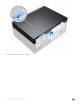
2 Removing and installing components This section provides detailed information on how to remove or install the components from your computer. Recommended tools The procedures in this document require the following tools: • Small flat blade screwdriver • Phillips # 1 screwdriver • Small plastic scribe Back cover Removing cover 1 Follow the procedure in Before working inside your computer. 2 To release the cover: a b Slide the blue tab to release the cover from the computer [1].
3 10 Lift the cover to remove it from the computer.
Installing cover 1 Place the cover on the computer and slide the cover forward until it clicks into place. 2 Follow the procedure in After working inside your computer. Front Bezel Removing bezel 1 Follow the procedure in Before working inside your computer. 2 Remove the cover. 3 To remove the bezel: a b Lift the tabs to release the bezel from the chassis [1]. Push the bezel away from the chassis [2].
Installing bezel 1 Position the bezel to align the tab holders on the chassis. 2 Press the bezel until the tabs click into place. 3 Install the cover. 4 Follow the procedure in After working inside your computer. Opening the front panel door 1 Follow the procedure in Before working inside your computer. 2 Remove the: a b cover bezel CAUTION: The front panel door opens only to a limited extent. See the printed image on the front panel door for the maximum permissible level.
Storage Removing 3.5–inch hard drive assembly 1 Follow the procedure in Before working inside your computer. 2 Remove the: a b 3 cover bezel To remove the hard drive assembly: a Disconnect the hard drive assembly cables from the connectors on the hard drive.
b 14 Press the blue tab [1] and pull the hard drive assembly out of the computer [ 2].
Removing 3.5–inch hard drive from the hard drive bracket 1 Follow the procedure in Before working inside your computer. 2 Remove the: a b c 3 cover bezel hard drive assembly To remove the hard drive bracket: a b Pull one side of the hard drive bracket to disengage the pins on the bracket from the slots on the hard drive [1]. Lift the hard drive out of the hard drive bracket [2].
Installing 3.5–inch hard drive assembly 1 Insert the hard drive assembly into the slot on the computer until it clicks into place. 2 Close the front panel door. 3 Connect the SATA cable and the power cable to the connectors on the hard drive. 4 Install the: a b 5 bezel cover Follow the procedure in After working inside your computer. Installing the 3.
Removing the 2.5–inch drive from the drive bracket 1 Follow the procedure in Before Working Inside Your Computer. 2 Remove the: a b c 3 cover bezel 2.5–inch drive assembly To remove the drive: a b Pull one side of the drive bracket to disengage the pins on the bracket from the slots on the drive [1]. Lift the drive out of the drive bracket [2].
Installing the 2.5-inch drive assembly 1 Insert the drive assembly into the slot on the computer until it clicks into place. 2 Close the front panel door. 3 Connect the SATA cable and the power cable to the connectors on the drive. 4 Install the: • 5 bezel • cover Follow the procedure in After Working Inside Your Computer. Optical drive Removing optical drive 1 Follow the procedure in Before working inside your computer. 2 Remove the: a b cover bezel 3 Open the front panel door.
c Press the blue release tab [1] and slide the optical drive out of the computer [2].
Installing optical drive 1 Insert the optical drive into the optical drive bay until it clicks into place. 2 Open the front panel door. 3 Route the data cable and power cable under the drive cage. 4 Connect the data cable and power cable to the connectors on the optical drive. 5 Close the front panel door. 6 Install the: a b 7 bezel cover Follow the procedure in After working inside your computer. M.2 PCIe SSD Removing optional M.
3 Open the front panel door. 4 To remove the M.2 PCIe SSD: a b Pull the blue tab that secures the M.2 PCIe SSD to the system board [1]. Disconnect the M.2 PCIe SSD from the connector on the system board [2]. Installing optional M.2 PCIe SSD 1 Insert the M.2 PCIe SSD to the connector. 2 Press the blue tab to secure the M.2 PCIe SSD. 3 Close the front panel door. 4 Install the: a b 5 bezel cover Follow the procedure in After working inside your computer.
SD card reader Removing SD card reader 1 Follow the procedure in Before working inside your computer. 2 Remove the: a b cover bezel 3 Open the front panel door. 4 To remove the SD card reader: a b c 22 Disconnect the SD card reader cable from the connector on the system board [1]. Remove the screw that secures the SD card reader to the front panel door [2]. Lift the SD card reader out of the computer [3].
Installing SD card reader 1 Insert the SD card reader into the slot on the system board. 2 Tighten the screw to secure the SD card reader to the front panel door. 3 Connect the SD card reader cable to the connector on the system board. 4 Close the front panel door. 5 Install the: a b 6 bezel cover Follow the procedure in After working inside your computer. Memory module Removing memory module 1 Follow the procedure in Before working inside your computer.
Expansion card Removing PCIe expansion card 1 Follow the procedure in Before working inside your computer. 2 Remove the: a b cover bezel 3 Open the front panel door. 4 To remove the PCIe expansion card: a b Pull the release latch to unlock the PCIe expansion card [1]. Push the card retention latch [2], and lift the PCIe expansion card out of the computer [3]. NOTE: This step is applicable only for the connector with card retention latch, otherwise, lift the PCIe expansion card out of the computer.
Installing PCIe expansion card 1 Pull the release latch backward to open [1]. 2 To remove the PCIe brackets (1 and 3) as shown below, insert a screwdriver in the hole of a PCIe bracket and push hard to release the bracket [2], and then lift the bracket out from your computer. NOTE: To remove the PCIe brackets (2 and 4), push the bracket upwards from the inside of your computer to release it and then lift the bracket away from your computer.
9 Follow the procedure in After working inside your computer. Power supply unit Removing power supply unit (PSU) 1 Follow the procedure in Before working inside your computer. 2 Remove the: a b cover bezel 3 Open the front panel door. 4 To release the PSU: a b c d 5 To remove the PSU: a b 26 Disconnect the PSU cables from the connectors on the system board [1] [2]. Pull the release clip [3]. Unroute the PSU cables from the retention clip [4].
Installing power supply unit (PSU) 1 Insert the PSU into the PSU slot and slide it toward the back of the computer until it clicks into place. 2 Tighten the screws to secure the PSU to the computer. 3 Route the PSU cables through the retention clips. 4 Connect the PSU cables to the connectors on the system board. 5 Close the front panel door. 6 Install the: a b 7 bezel cover Follow the procedure in After working inside your computer.
VGA daughter board Removing VGA daughter board 1 Follow the procedure in Before working inside your computer. 2 Remove the: a b cover bezel 3 Open the front panel door 4 To remove the VGA daughter board: a b c d 28 Remove the screws that secure the VGA connector to the computer [1]. Slide the VGA connector to release it from the computer. Remove the screw that secures the VGA daughter board to the computer [2]. Lift the VGA daughter board using the handle to remove it from the computer [3].
Installing VGA daughter board 1 Align the VGA daughter board with the screw holder on the system board. 2 Tighten the screw to secure the VGA daughter board to the system board. 3 Insert the VGA connector into the slot at the back of the computer. 4 Tighten the screws to secure the VGA connector to the computer. 5 Close the front panel door. 6 Install the: a b 7 bezel cover Follow the procedure in After working inside your computer.
Installing intrusion switch 1 Insert the intrusion switch into the slot on the computer. 2 Route the intrusion switch cable through the fan grommet. 3 Connect the intrusion switch cable to the connector on the system board. 4 Close the front panel door. 5 Install the: a b 6 bezel cover Follow the procedure in After working inside your computer. Power switch Removing power switch 1 Follow the procedure in Before working inside your computer.
a b cover bezel 3 Open the front panel door. 4 To release the power switch: a b c d 5 Disconnect the power switch cable from the system board [1]. Unroute the power switch cable through the retention clip [2]. Press the release tabs using a plastic scribe and slide the power switch out from the front of the computer [2,3]. Close the front panel door [4]. Pull the power switch out from the computer.
Installing power switch 1 Insert the power switch into the slot from the front of the computer and press it until it clicks into place. 2 Route the power switch cable through the retention clip. 3 Align the cable with the pins on the connector and connect the cable. 4 Close the front panel door. 5 Install the: a b 6 bezel cover Follow the procedure in After working inside your computer. Speaker Removing speaker 1 Follow the procedure in Before working inside your computer.
3 Open the front panel door. 4 To remove the speaker: a b Disconnect the speaker cable from the connector on the system board [1]. Close the front panel door. c Press the release tabs [1], and slide the speaker [2] out of the slot.
Installing speaker 1 Insert the speaker into the slot and press it until it clicks into place. 2 Connect the speaker cable to the connector on the system board. 3 Close the front panel door. 4 Install the: a b 5 bezel cover Follow the procedure in After working inside your computer. Coin cell battery Removing coin cell battery 1 Follow the procedure in Before working inside your computer. 2 Remove the: a b 3 34 cover bezel Open the front panel door.
4 To remove the coin cell battery: a b Press the release latch until the coin cell battery pops out [1]. Remove the coin cell battery from the connector on the system board [2]. Installing the coin cell battery 1 Hold the coin cell battery with the "+" sign facing up and slide it under the securing tabs at the positive side of the connector. 2 Press the battery into the connector until it locks into place. 3 Close the front panel door.
Heat sink assembly Removing heat sink assembly 1 Follow the procedure in Before working inside your computer. 2 Remove the: a b cover bezel 3 Open the front panel door. 4 To remove the heat sink assembly: a b c 36 Disconnect the heat sink assembly cable from the connector on the system board [1]. Loosen the captive screws that secure the heat sink assembly to the system board [2]. Lift the heat sink assembly away from the computer [3].
Installing heat sink assembly 1 Align the screws of the heat sink assembly with the holders on the system board. 2 Place the heat sink assembly on the processor. 3 Tighten the captive screws to secure the heat sink assembly to the system board. 4 Connect the heat sink assembly cable to the connector on the system board. 5 Close the front panel door. 6 Install the: a b 7 bezel cover Follow the procedure in After working inside your computer.
Installing processor 1 Align the processor with the socket keys. CAUTION: Do not use force to seat the processor. When the processor is positioned correctly, it engages easily into the socket. 2 Align the pin-1 indicator of the processor with the triangle on the socket. 3 Place the processor on the socket such that the slots on the processor align with the socket keys. 4 Close the processor shield by sliding it under the retention screw.
System fan Removing system fan 1 Follow the procedure in Before working inside your computer. 2 Remove the: a b c cover bezel intrusion switch 3 Open the front panel door. 4 To remove the system fan: a b c d Disconnect the system fan cable from the connector on the system board [1]. Remove the tape that holds the intrusion switch cable on the system fan and move the cable away. Stretch the grommets securing the fan to the computer to ease the removal of the fan [2].
Installing system fan 1 Insert the grommets into the slots on the back of the computer. 2 Hold the system fan with the cable facing the bottom of the computer. 3 Align the grooves of the system fan with the grommets on the chassis wall. 4 Pass the grommets through the corresponding grooves on the system fan. 5 Stretch the grommets and slide the system fan toward the computer until it locks into place. 6 Secure the intrusion switch cable to the system fan with an adhesive tape.
6 Disconnect the following cables from the system board: a b c d e f g PSU [1] power switch [2] speaker [3] PSU [4] power distribution for optical drive and hard drive [5] system fan [6] intrusion switch [7] Removing and installing components 41
7 To remove the system board: a b 42 Remove the screws that secure the system board to the computer [1]. Slide and lift the system board away from the computer [2].
Installing the system board 1 Hold the system board by its edges and align it toward the back of the computer. 2 Lower the system board into the computer until the connectors at the back of the system board align with the slots on the chassis, and the screw holes on the system board align with the standoffs on the computer. 3 Tighten the screws to secure the system board to the computer. 4 Route all the cables through the routing clips.
a b c d e f g memory module optional M.2 PCIe SSD expansion card SD card reader processor heat sink assembly VGA daughter board 7 Close the front panel door. 8 Install the: a b 9 44 bezel cover Follow the procedure in After working inside your computer.
3 M.2 Intel Optane Memory Module 16 GB Overview This document describes the specifications and capabilities of the Intel® OptaneTM memory module. The Intel® OptaneTM memory is a system acceleration solution developed for 7th Generation Intel® CoreTM processor-based platforms. The Intel® OptaneTM memory module is architected with the high performance controller interface Non-Volatile Memory Express (NVMe*)- delivering outstanding performance, low latency and quality of service.
b Place the thermal pad on the SSD slot and remove the white adhesive tape. c Place the M.2 Intel optane memory module into the slot on the thermal pad. M.
d If the system is shipped with screw tighten that secures the M.2 Intel optane memory module on the computer. If the system is shipped with self locking spacer press to lock the M.2 Intel optane to secure on the computer. Product specifications Features Specification Capacities 16 GB, 32 GB Expansion cards PCIe 3.0 x 2 M.
Supported Platforms 7th generation or newer Intel Core processor based platforms Power • • • 3.3V Supply Rail Active: 3.5 W Drive Idel :900mW to 1.2W Compliance • • • NVMe Express 1.1 PCI Express Base specifiation rev 3.0 PCI M.2 HS Spec Certification and Declarationsµ UL, CE, C-Tick, BSMI, KCC, Microsoft WHQL, Microsoft WHCK, VCCI Endurance Rating • • 100 GB Writes per day Upto 182.
Operating 1500 G / 0.5 ms Non-operating 230 G / 3 msec Vibration5 Operating 2.17 GRMS (5–800Hz) Max Non-operating 3.13 GRMS (5–800Hz) Max NOTES: 1 Operating temperature is targeted for 70º C. 2 Please contact your Intel representative for details on the non-operating temperature range. 3 Temperature gradient measured without condensation. 4 Shock specification assume the device is mounted securely with the input vibration applied to the drive-mounting screws.
4 Technology and components USB features The Universal Serial Bus, or well known as USB was introduced to the PC world in 1996 which dramatically simplified the connection between host computer and peripheral devices such as mice and keyboards, external hard drive or optical devices, Bluetooth and many more peripheral devices in the market. Let's take a quick look on the USB evolution referencing to the table below. Table 3. USB evolution Type Data Transfer Rate Category Introduction Year USB 3.0/USB 3.
commonly known as USB 2.0 and 1.1 respectively, the slower modes still operate at 480Mbps and 12Mbps respectively and are kept to maintain backward compatibility. USB 3.0/USB 3.1 Gen 1 achieves the much higher performance by the technical changes below: • An additional physical bus that is added in parallel with the existing USB 2.0 bus (refer to the picture below). • USB 2.0 previously had four wires (power, ground, and a pair for differential data); USB 3.0/USB 3.
Compatibility The good news is that USB 3.0/USB 3.1 Gen 1 has been carefully planned from the start to peacefully co-exist with USB 2.0. First of all, while USB 3.0/USB 3.1 Gen 1 specifies new physical connections and thus new cables to take advantage of the higher speed capability of the new protocol, the connector itself remains the same rectangular shape with the four USB 2.0 contacts in the exact same location as before.
• Audio HDMI supports multiple audio formats from standard stereo to multichannel surround sound • HDMI combines video and multichannel audio into a single cable, eliminating the cost, complexity, and confusion of multiple cables currently used in A/V systems • HDMI supports communication between the video source (such as a DVD player) and the DTV, enabling new functionality Technology and components 53
5 System setup System Setup enables you to manage your desktop hardware and specify BIOS level options.
Table 4. Navigation Keys Keys Navigation Up arrow Moves to the previous field. Down arrow Moves to the next field. Allows you to select a value in the selected field (if applicable) or follow the link in the field. Spacebar Expands or collapses a drop‐down list, if applicable. Moves to the next focus area. NOTE: For the standard graphics browser only. Moves to the previous page till you view the main screen.
Deleting or changing an existing system and/or setup password Ensure that the Password Status is Unlocked (in the System Setup) before attempting to delete or change the existing System and/or Setup password. You cannot delete or change an existing System or Setup password, if the Password Status is Locked. To enter the System Setup, press F2 immediately after a power-on or reboot. 1 In the System BIOS or System Setup screen, select System Security and press Enter. The System Security screen is displayed.
Table 6. System Configuration Option Description Integrated NIC Allows you to control the on-board LAN controller. The option ‘Enable UEFI Network Stack’ is not selected by default. The options are: • • • Disabled Enabled Enabled w/PXE (default) NOTE: Depending on the computer and its installed devices, the items listed in this section may or may not appear. SATA Operation Allows you to configure the operating mode of the integrated hard drive controller.
Option Description • • • Enable PCI Slot (default option) Enable Media Card (default option) Disable Media Card Table 7. Video Option Description Primary Display Allows you to select the primary display when multiple controllers are available in the system. • • Auto (default) Intel HD Graphics NOTE: If you do not select Auto, the on-board graphics device will be present and enabled. Table 8. Security Option Description Admin Password Allows you to set, change, and delete the admin password.
Option Description • • • Computrace SHA-256(default) Disabled Enabled (default) This field lets you Activate or Disable the BIOS module interface of the optional Computrace Service from Absolute Software. Enables or disables the optional Computrace service designed for asset management. • • • Chassis Intrusion Deactivate - This option is selected by default. Disable Activate Allows you to control the chassis intrusion feature.
Option Description NOTE: If you disable the Custom Mode, all the changes made will be erased and the keys will restore to default settings. Table 10. Intel Software Guard Extensions Option Description Intel SGX Enable Allows you to enable or disable the Intel Software Guard Extensions to provide a secured environment for running code/storing sensitive information in the context of the main operating system.
Option Description This option is Power Off by default. Auto On Time Sets time to automatically turn on the computer. Time is kept in standard 12-hour format (hour:minutes:seconds). Change the startup time by typing the values in the time and AM/PM fields. NOTE: This feature does not work if you turn off your computer using the switch on a power strip or surge protector or if Auto Power is set to disabled. Deep Sleep Control Allows you to define the controls when Deep Sleep is enabled.
Table 14. Manageability Option Description USB provision This option is not selected by default. MEBx Hotkey This option is selected by default. Table 15. Virtualization Support Option Description Virtualization This option specifies whether a Virtual Machine Monitor (VMM) can utilize the additional hardware capabilities provided by Intel® Virtualization Technology. Enable Intel Virtualization Technology This option is enabled by default.
Updating the BIOS in Windows It is recommended to update your BIOS (System Setup), on replacing the system board or if an update is available. For laptops, ensure that your computer battery is fully charged and connected to a power outlet NOTE: If BitLocker is enabled, it must be suspended prior to updating the system BIOS, and then re-enabled after the BIOS update is completed. 1 Restart the computer. 2 Go to Dell.com/support. • Enter the Service Tag or Express Service Code and click Submit.
Figure 1. DOS BIOS Update Screen Enabling smart power on To enable Smart Power On and the ability to wake a system from S3, S4, and S5 sleep states with a move of a mouse or press of a key on the keyboard, perform these steps: 1 Make sure the following BIOS settings under Power Management setup option are set as mentioned here: • USB Wake Support as Enabled. • Deep Sleep Control as Disabled.
6 Software Supported operating systems The following list shows supported operating systems: Table 19. Supported operating system Supported operating systems Microsoft Windows Operating System Description • • • Microsoft Windows 10 Home (64-bit) Microsoft Windows 10 (64-bit) Professional Microsoft Windows 7 (32/64 bit) Professional NOTE: Microsoft Windows 7 is not supported with the Intel 7th Generation processors. Other OS Media Support • • Ubuntu 16.04 LTS Neokylin V6.
7 Click Download File to download the latest version of the chipset driver for your computer. 8 After the download is complete, navigate to the folder where you saved the driver file. 9 Double-click the chipset driver file icon and follow the instructions on the screen. Intel chipset drivers Verify if the Intel chipset drivers are already installed in the computer. NOTE: Click Start > Control Panel > Device Manager or In Search the web and Windows, type Device Manager Table 20.
Intel HD Graphics drivers Verify if the Intel HD Graphics drivers are already installed in the computer. NOTE: Click Start > Control Panel > Device Manager. or Tap Search the web and Windows and type Device Manager Table 21. Intel HD Graphics drivers Before installation After installation Intel Wi-Fi and Bluetooth drivers In the Device Manager, check if the network card driver is installed. Install the driver updates from dell.com/support.
NOTE: If you do not have the Service Tag, use the auto-detect feature or manually browse for your computer model. 4 Click Drivers & downloads > Find it myself. 5 Scroll down the page and expand Network. 6 Click Download to download the Wi-Fi driver for your computer. 7 After the download is complete, navigate to the folder where you saved the Wi-Fi driver file. 8 Double-click the driver file icon and follow the instructions on the screen.
7 Troubleshooting your computer You can troubleshoot your computer using indicators like diagnostic lights, and error messages during the operation of the computer. Diagnostic power LED codes Table 23. Diagnostic power LED codes Power LED light status Possible cause Troubleshooting steps Off The computer is either turned • off or is not receiving power or in Hibernation mode. • • Steady/blinking amber Computer fails to complete POST or processor failure.
Power LED light status Possible cause Troubleshooting steps • If the display is connected and turned on, listen for a beep code. Power LED issue Power LED is not flashing amber on ChengMing 3977 and Optiplex D8 and OptiPlex D8 AIO platforms. ChengMing 3977 and OptiPlex D8 and D8 AIO platforms without processor installed or when processor power cable is not connected; it may not have the power LED flashing amber as the diagnostic indicator.
Diagnostic error messages Table 24. Diagnostic error messages Error messages Description AUXILIARY DEVICE FAILURE The touchpad or external mouse may be faulty. For an external mouse, check the cable connection. Enable the Pointing Device option in the System Setup program. BAD COMMAND OR FILE NAME Ensure that you have spelled the command correctly, put spaces in the proper place, and used the correct path name. CACHE DISABLED DUE TO FAILURE The primary cache internal to the microprocessor has failed.
Error messages Description persists, try another drive. Run the Hard Disk Drive tests in Dell Diagnostics. HARD-DISK DRIVE FAILURE The hard drive does not respond to commands from the computer. Shut down the computer, remove the hard drive, and boot the computer from an optical drive. Then, shut down the computer, reinstall the hard drive, and restart the computer. If the problem persists, try another drive. Run the Hard Disk Drive tests in Dell Diagnostics.
Error messages Description NO BOOT DEVICE AVAILABLE The computer cannot find the hard drive. If the hard drive is your boot device, ensure that the drive is installed, properly seated, and partitioned as a boot device. NO BOOT SECTOR ON HARD DRIVE The operating system may be corrupted, Contact Dell. NO TIMER TICK INTERRUPT A chip on the system board may be malfunctioning. Run the System Set tests in Dell Diagnostics. NOT ENOUGH MEMORY OR RESOURCES.
System error messages Table 25. System error messages System message Description Alert! Previous attempts at booting this system The computer failed to complete the boot routine three consecutive have failed at checkpoint [nnnn]. For help in times for the same error. resolving this problem, please note this checkpoint and contact Dell Technical Support CMOS checksum error RTC is reset, BIOS Setup default has been loaded. CPU fan failure CPU fan has failed. System fan failure System fan has failed.
Verifying system memory in setup 1 Turn on or restart your computer. 2 Perform one of the following actions after the Dell logo is displayed: 3 • With keyboard — Tap F2 until the Entering BIOS setup message appears. To enter the Boot selection menu, tap F12. On the left pane, select Settings > General > System Information, The memory information is displayed on the right pane. Testing memory using ePSA 1 Turn on or restart your computer. 2 After the Dell logo is displayed: a b Press F12.
8 Technical specifications NOTE: Offerings may vary by region. For more information regarding the configuration of your computer in: • Windows 10, click or tap Start > Settings > System > About.
Memory specifications Feature Specification Type 2133 MHz / 2400 MHz NOTE: 2133 MHz is applicable only for 6th Generation processors.
Storage specifications Feature Specification Hard drive one 3.5-inch hard drive and one 2.5-inch drive Solid State Drive one M.2 Solid State Drive Optical drive one slim drive and one 5.25-inch drive Ports and connectors specifications Table 27. Ports and connectors Feature Specification Front I/O ports Rear I/O ports Universal audio jack One USB 3.1 Gen 1 Two (one with Type-C) USB 2.0 Two (one with PowerShare) USB 3.1 Gen 1 Four USB 2.
Feature Specification Weight 9.43 kg (20.96 lb) System board layout 1 PCIe x16(wire x4) connector (slot4) 2 PCI connector (slot3) 3 PCIe x16 connector (slot2) 4 PCI-eX1 connector (slot 1) 5 VGA Daughter Board Connector (VGA) 6 System fan connector 7 Intrusion switch connector 8 Processor 9 CPU power connector 10 CPU fan connector 11 Coin cell battery 12 Memory module connectors 13 Card reader connector 14 Power switch connector 15 M.
Controls and lights specifications Feature Specification Power button light White light — Solid white light indicates power-on state; blinking white light indicates sleep state of the computer. Hard Drive activity light White light — Blinking white light indicates that the computer is reading data from or writing data to the hard drive. Back panel: Link integrity light on Green — a good 10 Mbps or 100 Mbps connection exists between the network and the computer.
9 Contacting Dell NOTE: If you do not have an active Internet connection, you can find contact information on your purchase invoice, packing slip, bill, or Dell product catalog. Dell provides several online and telephone-based support and service options. Availability varies by country and product, and some services may not be available in your area. To contact Dell for sales, technical support, or customer service issues: 1 Go to Dell.com/support. 2 Select your support category.