
User Guide
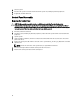
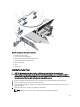

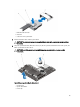
Table Of Contents
- Dell PowerVault DL4000 Systems Owner's Manual
- About Your System
- Using The System Setup And Boot Manager
- Installing System Components
- Recommended Tools
- Front Bezel (Optional)
- Opening And Closing The System
- Inside The System
- Cooling Shroud
- System Memory
- Hard Drives
- Cooling Fans
- Expansion Cards And Expansion-Card Risers
- SD vFlash Card
- Internal Dual SD Module
- Internal SD Card
- Integrated Storage Controller Card
- Network Daughter Card
- Processors
- Power Supplies
- System Battery
- Hard-Drive Backplane
- Control Panel Assembly
- System Board
- Troubleshooting Your System
- Safety First—For You And Your System
- Troubleshooting System Startup Failure
- Troubleshooting External Connections
- Troubleshooting The Video Subsystem
- Troubleshooting A USB Device
- Troubleshooting A Serial I/O Device
- Troubleshooting A NIC
- Troubleshooting A Wet System
- Troubleshooting A Damaged System
- Troubleshooting The System Battery
- Troubleshooting Power Supplies
- Troubleshooting Cooling Problems
- Troubleshooting Cooling Fans
- Troubleshooting System Memory
- Troubleshooting An SD Card
- Troubleshooting A Hard Drive
- Troubleshooting A Storage Controller
- Troubleshooting Expansion Cards
- Troubleshooting Processors
- Using System Diagnostics
- Jumpers And Connectors
- Technical Specifications
- System Messages
- Getting Help
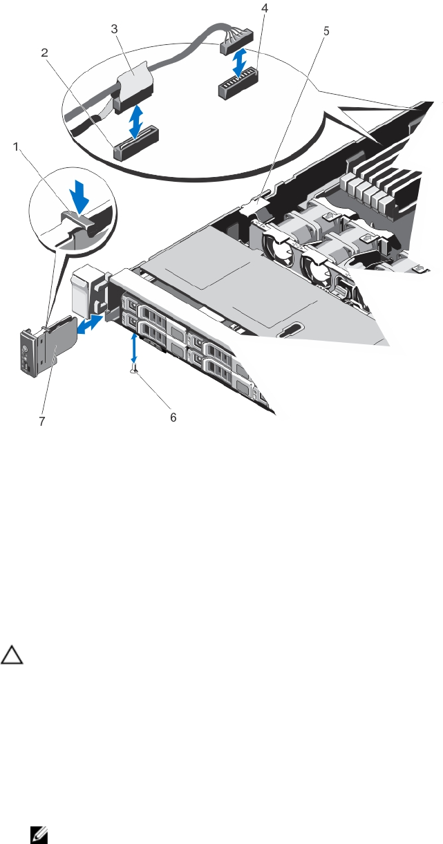
Figure 31. Removing and Installing the Control Panel
1. control panel release latch
2. J_CP connector on system board
3. control panel cable connecting to system board
4. J_FP_USB connector on system board
5. cable securing clip
6. screw
7. control panel
Installing The Control Panel
CAUTION: Many repairs may only be done by a certified service technician. You should only perform
troubleshooting and simple repairs as authorized in your product documentation, or as directed by the online or
telephone service and support team. Damage due to servicing that is not authorized by Dell is not covered by your
warranty. Read and follow the safety instructions that came with the product.
1. Route the control panel cable through the chassis and connect the control panel cable to the control panel.
2. Push the control panel into the chassis till it snaps into place.
3. Using a #1 Philips screwdriver, replace the screw (located at the bottom of the chassis) that secures the control
panel to the chassis.
4. Locate the connectors J_CP and J_FP_USB on the system board.
NOTE: To locate the connectors on the system board, see System Board Connectors.
63