
Install Guide


4. Turn on the controller and make sure the controller is operational. See Turning On Power to a Controller on
page 36.
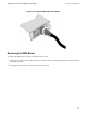
5. Attach the controller bezel. See Attaching the Controller Bezel on page 26.
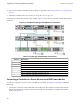
The following sections describe these steps in detail. Figure 31 shows the two controllers and the BPS properly
connected.
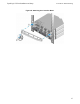
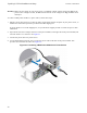
Figure 31: Complete EqualLogic FS7500Power Connections
Table 11: EqualLogic FS7500 Power Connections
Callout Description
1 USB connection from Controller 1 to BPS power module 1
2 Power connection from Controller 1 to BPS power module 1
3 Power connection from Controller 1 to Power Source 1
4 USB connection from Controller 2 to BPS power module 2
5 Power connection from Controller 2 to BPS power module 2
6 Power connection from Controller 2 to Power Source 2
7 Power connection from BPS to Power Source 2
8 Power connection from BPS to Power Source 1
Connecting a Controller to a Power Source and a BPS Power Module
To connect a controller to a power source and a BPS power module, see Figure 31 and Table 11 and follow
these steps:
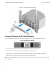
1. Connect the A connector on the USB cable to the USB port on the controller (located to the left of the
bottom network interface card) and connect the B connector to the USB port on a BPS power module
(callout 1 in Figure 31).
34
EqualLogic FS7500 Installation and Setup
3 Power Connections