
Install Guide

EqualLogic FS7500 Installation and Setup
4 Network Cable Connections
Note: If you use VLANs within your switch stack, the internal and SAN networks must be in the same VLAN.
Connecting SAN and Internal Network Cables
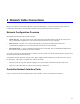
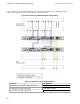
See Figure 34 on page 40. For each controller, make the following controller connections to the two switch
stacks:
• The ports labeled Eth30, Eth31, Eth32, and Eth33 on the two top network interface cards.
• Single port in the lower-left corner of the controller.
Connecting the Client Network Cables
See Callout 1 in Figure 34 on page 40.
For each controller, use four network cables to connect all the ports on the bottom network interface card to a
switch stack that is different from the switch stack for the SAN and internal network connections.
Managing the Controller Cables
There are three main methods of managing the controller cables in the EqualLogic FS7500. The three methods
differ in how the controller cables are routed and secured. The three methods are:
• Cabling the FS7500 installed in sliding rails. This is the standard installation as described in Hardware Rack
Mounting on page 1, using the rails provided in the shipping box. The cable connections are described in
Steps for Connecting Network Cables on page 39.
• Adding a service loop to the FS7500 controller installed in the provided rails. A service loop is an extra
length of cable between the rear of the controller and the rack. The additional cable allows you to slide the
controller forward on the rails for servicing without having to disconnect the cables and power cables.
• Cabling the FS7500 controller installed in static rails. This method requires a different set of rails that must
be ordered separately. Appendix 1, Custom Racking Instructions, describes how to manage cables on
controllers that are installed in static rails.
For more information about routing controller cables, see the Dell white paper Dell Best Practices Guide for
Rack Enclosures. This white paper is available online in the Dell Storage Document Center at
http://www.dellstorage.com/resources/document-center.aspx.
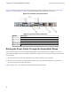
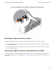
Steps for Managing Cables in a Standard Installation
Cable management for the FS7500 controller consists of the following steps:
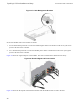
• Route the power cables through the strain relief straps
• Bundle the signal and power cables together using the hook-and-loop fasteners supplied in the shipping box
• Secure the signal and power cable bundles to the rails
41