Dell™ Inspiron™ i1200 and i2200 Service Manual Before You Begin System Components Memory, Optical Drive, Modem, and Mini PCI Card Hard Drive Keyboard Display Palm Rest Coin-Cell Battery Microprocessor Thermal-Cooling Assembly Microprocessor Module Speakers System Board Flashing the BIOS Base Plastics Pinout Assignments for I/O Connectors NOTE: A NOTE indicates important information that helps you make better use of your computer.
Back to Contents Page Base Plastics Dell™ Inspiron™ i1200 and i2200 Service Manual CAUTION: Before performing the following procedures, read the safety instructions in the Product Information Guide. CAUTION: To prevent static damage to components inside your computer, discharge static electricity from your body before you touch any of your computer's electronic components. You can do so by touching an unpainted metal surface. 1. Follow the instructions in "Before Working Inside Your Computer." 2.
Back to Contents Page Before You Begin Dell™ Inspiron™ i1200 and i2200 Service Manual Recommended Tools Turning Off Your Computer Before Working Inside Your Computer Computer Orientation Screw Identification This chapter provides procedures for removing and installing the components in your computer. Unless otherwise noted, each procedure assumes that the following conditions exist: l You have performed the steps in "Turning Off Your Computer" and "Before Working Inside Your Computer.
NOTICE: Only a certified service technician should perform repairs on your computer. Damage due to servicing that is not authorized by Dell is not covered by your warranty. NOTICE: When you disconnect a cable, pull on its connector or on its strain-relief loop, not on the cable itself. Some cables have a connector with locking tabs; if you are disconnecting this type of cable, press in on the locking tabs before you disconnect the cable.
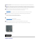
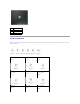
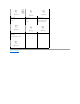
1 front 2 left 3 back 4 right Screw Identification When you are removing and replacing components, print this section as a tool to lay out and keep track of the screws. The placemat provides the number of screws and their sizes.
Screw Covers (6 each) Display Bumpers (6 each) Palm Rest to Base Plastics: Palm Rest to Base Plastics in Hard Drive Bay: System Board to Base Plastics: (8 each) (2 each) (4 each, hard drive cage) (2 each, system board) Speakers to Base Plastics: (2 for each speaker, 4 total) Back to Contents Page
Back to Contents Page Flashing the BIOS Dell™ Inspiron™ i1200 and i2200 Service Manual Flashing the BIOS From a Floppy Disk or a CD Flashing the BIOS From the Hard Drive If a BIOS-update program floppy disk or CD is provided with the new system board, flash the BIOS from a floppy disk or a CD. If you do not have a BIOS-update program floppy disk or CD, flash the BIOS from the hard drive. Flashing the BIOS From a Floppy Disk or a CD 1.
Back to Contents Page
Back to Contents Page Coin-Cell Battery Dell™ Inspiron™ i1200 and i2200 Service Manual CAUTION: Before performing the following procedures, read the safety instructions in the Product Information Guide. CAUTION: To prevent static damage to components inside your computer, discharge static electricity from your body before you touch any of your computer's electronic components. You can do so by touching an unpainted metal surface. 1. Follow the instructions in "Before Working Inside Your Computer.
Back to Contents Page Microprocessor Module Dell™ Inspiron™ i1200 and i2200 Service Manual Removing the Microprocessor Module Installing the Microprocessor Module Removing the Microprocessor Module CAUTION: Before performing the following procedures, read the safety instructions in the Product Information Guide. CAUTION: To prevent static damage to components inside your computer, discharge static electricity from your body before you touch any of your computer's electronic components.
Installing the Microprocessor Module NOTICE: Ensure that the cam lock is in the fully open position before seating the microprocessor module. Seating the microprocessor module properly in the ZIF socket does not require force. NOTICE: A microprocessor module that is not properly seated can result in an intermittent connection or permanent damage to the microprocessor and ZIF socket. 1.
Back to Contents Page Display Dell™ Latitude™ 110L Service Manual Display Assembly Display Bezel Display Panel Display Assembly CAUTION: Before performing the following procedures, read the safety instructions in the Product Information Guide. CAUTION: To prevent static damage to components inside your computer, discharge static electricity from your body before you touch any of your computer's electronic components. You can do so by touching an unpainted metal surface. 1.
1 M2.5 x 5-mm screws (4) 2 shield retention tabs (3) 3 shield-retention tab slots 6. Disconnect the attached antenna cable from the Mini PCI card. 1 antenna cable 2 metal securing tabs (2) 3 Mini PCI card connector 4 Mini PCI card 7. Close the display. 8. From the bottom of the computer, remove the two M2.5 x 5-mm screws labeled "D.
9. From the back of the computer, remove the two M2.5 x 8-mm screws labeled "D." 10. Pull straight up on the pull-tab that is attached to the display-feed flex cable to disconnect the cable from the system board. 1 display cable 2 system board connector 11. Carefully remove the Mini PCI card antenna cable and the display cables from their routing guides. 12. Lift the display assembly out of the computer base.
1 screw covers/display bumpers (6) 2 display bezel 3 M2.5 x 5-mm screws (6) 4 display panel 5 M2 x 3-mm screws (8) 6 top cover 7 display-feed flex cable Display Bezel CAUTION: Before performing the following procedures, read the safety instructions in the Product Information Guide. CAUTION: To prevent static damage to components inside your computer, discharge static electricity from your body before you touch any of your computer's electronic components.
CAUTION: Before performing the following procedures, read the safety instructions in the Product Information Guide. CAUTION: To prevent static damage to components inside your computer, discharge static electricity from your body before you touch any of your computer's electronic components. You can do so by touching an unpainted metal surface. 1. Follow the instructions in "Before Working Inside Your Computer." 2. Remove the display assembly. 3. Remove the display bezel. 4.
Back to Contents Page Hard Drive Dell™ Inspiron™ i1200 and i2200 Service Manual Removing the Hard Drive Installing the Hard Drive Removing the Hard Drive CAUTION: If you remove the hard drive from the computer when the drive is hot, do not touch the metal housing of the hard drive. CAUTION: Before working inside your computer, follow the safety instructions located in the Product Information Guide. NOTICE: To prevent data loss, turn off your computer before removing the hard drive.
NOTE: You need the Drivers and Utilities CD to install the drivers and utilities on the new hard drive. The Drivers and Utilities CD is optional and may not ship with your computer. See your Owner's Manual for more information. 5. Remove the new drive from its packaging. Save the original packaging for storing or shipping the hard drive. NOTICE: Use firm and even pressure to slide the drive into place. If you use excessive force, you may damage the connector. 6.
Back to Contents Page Keyboard Dell™ Inspiron™ i1200 and i2200 Service Manual Removing the Keyboard Installing the Keyboard Removing the Keyboard CAUTION: Before working inside your Dell™ computer, read the safety instructions in your Product Information Guide. CAUTION: To prevent static damage to components inside your computer, discharge static electricity from your body before you touch any of your computer's electronic components. You can do so by touching an unpainted metal surface. 1.
NOTICE: The keycaps on the keyboard are fragile, easily dislodged, and time-consuming to replace. Be careful when removing and handling the keyboard. 6. Lift the top of the keyboard out of the computer base, and pull the keyboard out at an angle toward the display to access the connector. 7. Grasp the interface connector lever near the edge of the keyboard connector, and rotate the lever toward you to raise the interface connector lever. 8.
Back to Contents Page Palm Rest Dell™ Inspiron™ i1200 and i2200 Service Manual CAUTION: Before performing the following procedures, read the safety instructions in the Product Information Guide. CAUTION: To prevent static damage to components inside your computer, discharge static electricity from your body before you touch any of your computer's electronic components. You can do so by touching an unpainted metal surface. 1. Follow the instructions in "Before Working Inside Your Computer." 2.
10. Disconnect the touch pad connector from the system board. 1 connector lever 2 palm rest connector NOTICE: Carefully separate the palm rest from the base plastics to avoid damage to the palm rest. 11. Starting at the back center of the palm rest, use your fingers to separate the palm rest from the base plastics by lifting the inside edge of the palm rest.
Back to Contents Page Pinout Assignments for I/O Connectors Dell™ Inspiron™ i1200 and i2200 Service Manual USB Connector Video Connector USB Connector Pin Signal 1 USB5V+ 2 USBP– 3 USBP+ 4 GND Video Connector Pin Signal Pin Signal 1 CRT_R 9 5V+ 2 CRT_G 10 GND 3 CRT_B 11 MONITOR_DETECT– 4 NC 12 DDC_DATA 5 GND 13 CRT_HS 6 GND 14 CRT_VS 7 GND 15 DDC_CLK 8 GND Back to Contents Page
Back to Contents Page Speakers Dell™ Inspiron™ i1200 and i2200 Service Manual Removing the Speakers Installing the Speakers Removing the Speakers CAUTION: Before performing the following procedures, read the safety instructions in the Product Information Guide. CAUTION: To prevent static damage to components inside your computer, discharge static electricity from your body before you touch any of your computer's electronic components. You can do so by touching an unpainted metal surface.
Installing the Speakers 1. Slide the speakers down into the base plastics. NOTICE: Ensure that the speaker cables are under or between their routing clips. NOTE: The speakers face out in the base plastics holders. NOTE: The right speaker cable is longer than the left speaker cable. 2. Route the speaker cables under or between their routing clips. 3. Replace the four M2.5 x 5-mm screws. 4. Connect the speaker connector to the system board.
Back to Contents Page System Board Dell™ Inspiron™ i1200 and i2200 Service Manual Removing the System Board Installing the System Board Removing the System Board CAUTION: Before performing the following procedures, read the safety instructions in the Product Information Guide. CAUTION: To prevent static damage to components inside your computer, discharge static electricity from your body before you touch any of your computer's electronic components.
1 15. hex screws (2) Disconnect the display switch connector from the system board. 1 display switch connector 16. Remove any cards from the PCMCIA slot. 17. Remove the two M2.5 x 5-mm system board screws and lift the front of the system board out and away from the base plastics.
1 M2.5 x 5-mm screws (2) Installing the System Board 1. Insert the video connector on the replacement system board through the back of the base plastics. 2. Replace the two hex nuts that secure the video connector to the base plastics. 3. Replace the two M2.5 x 5-mm screws that secure the system board to the base plastics. 4. Replace the four M2.5 x 5-mm screws that secure the hard drive cage to the system board. 1 M2.5x5-mm screws (4) 2 hard drive cage 5.
7. Replace the palm rest. 8. Replace the microprocessor thermal-cooling assembly. 9. Replace the cooling fan. 10. Replace the display assembly. 11. Replace the keyboard. 12. Replace the Mini PCI card, modem, and memory module that you removed from the old system board. 13. Replace the optical drive. 14. Replace the hard drive. 15. Insert the battery into the battery bay. 16. Connect the AC adapter to the computer and to an electrical outlet.
Back to Contents Page System Components Dell™ Inspiron™ i1200 and i2200 Service Manual CAUTION: Only a certified service technician should perform repairs on your computer. Damage due to servicing that is not authorized by Dell is not covered by your warranty. NOTICE: Unless otherwise noted, each procedure in this document assumes that a part can be replaced by performing the removal procedure in reverse order.
Back to Contents Page Microprocessor Thermal-Cooling Assembly Dell™ Inspiron™ i1200 and i2200 Service Manual Removing the Cooling Fan Installing the Cooling Fan Removing the Microprocessor Thermal-Cooling Assembly Installing the Microprocessor Thermal-Cooling Assembly Removing the Cooling Fan CAUTION: Before performing the following procedures, read the safety instructions in the Product Information Guide.
1 M2.5 x 5-mm screws (4) 2 shield retention tabs (3) 3 shield-retention tab slots 6. Disconnect the two M2 x 3-mm screws and the fan power cable from the system board. . 1 M2 x 3-mm screws (2) 2 fan connector 7. Hold the fan by the plastic housing at an angle to lift it out of the system board. Installing the Cooling Fan 1. Align the cooling fan with the microprocessor thermal-cooling assembly on the system board. 2.
. 1 M2 x 3-mm screws (2) 2 fan connector 3. Align the EMI shield retention tabs with the retention-tab slots on the computer base and rotate the front until it lies flat. 4. Replace the four M2.5 x 5-mm screws that secure it to the system board. 1 M2.5 x 5-mm screws (4) 2 shield retention tabs (3) 3 shield-retention tab slots 1 M2.
1. Follow the instructions in "Before Working Inside Your Computer." 2. Remove the keyboard. 3. Disconnect the display ground wire from the EMI shield by unscrewing the captive screw. 1 captive screw 2 display ground wire 4. Remove the four M2.5 x 5-mm screws (labeled "M2.5x5") that secure the EMI shield to the system board, and pull the EMI shield out of the computer base. 1 M2.5 x 5-mm screws (4) 5. Remove the cooling fan. 6.
1 captive screws (4) 7. Pull up the microprocessor thermal-cooling assembly by the pull-tab to lift the assembly out of the system board. Installing the Microprocessor Thermal-Cooling Assembly NOTICE: Before you install the replacement microprocessor thermal-cooling assembly, remove the mylar that covers the thermal grease on the assembly. 1. If you are installing a replacement microprocessor thermal-cooling assembly, remove the mylar that covers the thermal grease on the assembly.
Back to Contents Page Dell™ Inspiron™ i1200 and i2200 Service Manual NOTE: A NOTE indicates important information that helps you make better use of your computer. NOTICE: A NOTICE indicates either potential damage to hardware or loss of data and tells you how to avoid the problem. CAUTION: A CAUTION indicates a potential for property damage, personal injury, or death. For a complete list of abbreviations and acronyms, see the Dell Inspiron Help file. To access the help file: 1.
Back to Contents Page Memory, Optical Drive, Modem, and Mini PCI Card Dell™ Inspiron™ i1200 and i2200 Service Manual Memory Optical Drive Modem Mini PCI Card Memory Removing the Memory Module CAUTION: Before working inside your Dell™ computer, read the safety instructions in the Product Information Guide. CAUTION: To prevent static damage to components inside your computer, discharge static electricity from your body before you touch any of your computer's electronic components.
1 securing clips 2 memory module Installing the Memory Modules NOTE: If the memory module is not installed properly, the computer may not boot properly. No error message indicates this failure. 1. Align the notch in the module edge connector with the tab in the connector slot. 2. Slide the module firmly into the slot at a 45-degree angle, and rotate the module down until it clicks into place. If you do not feel the click, remove the module and reinstall it. 3.
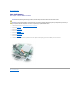
2. Remove the M2.5 x 8-mm screw from the indention labeled with a lock symbol ( 3. Insert a screwdriver into the indention and push the notch on the metal tab to release the drive from the bay. ). 1 notch 2 M2.5 x 8-mm screw labeled " " 3 optical drive 4. Pull the drive out of the bay. Installing the Optical Drive 1. Slide the new drive into the bay until it snaps securely into place. 2. Replace the M2.5 x 8-mm screw.
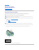
1 hinge cover 2 notched edge 3. Open the display all the way (180 degrees) so that it lies flat against your work surface. 4. Use a small plastic scribe to lift the right edge of the hinge cover. 5. Lift the hinge cover away from the hinges and computer base. 1 hinge cover 2 notched edge NOTICE: The keycaps on the keyboard are fragile, easily dislodged, and time-consuming to replace. Be careful when removing and handling the keyboard.
1 M2 x 3-mm screw 2 modem cable 3 pull-tab 4 captive screw Installing the Modem 1. Connect the modem cable to the modem. NOTICE: The cable connectors are keyed for correct insertion; do not force the connections. 2. Align the modem with the screw holes, and press the modem onto the connector on the system board. 3. Install the M2 x 3-mm screw to secure the modem to the system board. 4. Replace and tighten the captive screw on the opposite corner of the modem. 5.
1 captive screw 2 display ground wire 4. Remove the four M2.5 x 5-mm screws (labeled "M2.5x5") that secure the EMI shield to the system board. 5. Pull the EMI shield out of the computer baseby rotating the front upwards then lifting to release the retention tabs from the retention-tab slots. 1 M2.5 x 5-mm screws (4) 2 shield retention tabs (3) 3 shield-retention tab slots 6. Disconnect the attached antenna cable from the Mini PCI card.
1 antenna cable 2 metal securing tabs (2) 3 Mini PCI card connector 4 Mini PCI card 7. Use your fingertips to carefully spread apart the securing taps on each end of the Mini PCI card connector until the card pops up. 8. Lift the Mini PCI card out of its connector.
NOTICE: The connectors are keyed to ensure correct insertion. If you feel resistance, check the connectors and realign the card. 1. Align the Mini PCI card with the connector at a 45-degree angle, and press the Mini PCI card into the connector until it clicks. 1 Mini PCI card connector 2 Mini PCI card 2. Connect the antenna cable to the Mini PCI card. NOTE: To prevent damage to the antenna cable, ensure that the card is not on top of or under the cable. 3.
Back to Contents Page