Dell™ Console Switch Console Switch Installer/User’s Guide Model: Console Switch w w w. d e l l . c o m | s u p p o r t . d e l l .
Notes and Cautions Notes, Notices, and Cautions NOTE: A NOTE indicates important information that helps you make better use of your computer. NOTICE: A NOTICE indicates either potential damage to hardware or loss of data and tells you how to avoid the problem. CAUTION: A CAUTION indicates a potential for property damage, personal injury, or death. ___________________ Information in this document is subject to change without notice. © 2004 Dell Inc. All rights reserved.
Contents 1 Product Overview Features and Benefits . . . . . . . . . . . . . . . . . . . . . . . . . . . SIP Intelligent Module . . . . . . . . . . . . . . . . . . . . . . . . . . . Multiplatform Support . . . . . . OSCAR Graphical User Interface . Security . . . . . . . . . . . . Video . . . . . . . . . . . . . . Plug and Play . . . . . . . . . . FLASH Upgradable . . . . . . . Tiering Expansion . . . . . . . . Safety Precautions . . . . . . . . . . . . . . . . . . . . . . . . . . . . . . . . . . . . .
Viewing the Status of Your Switch Selecting Servers . . . . . . . . Soft Switching . . . . . . . . . Navigating the OSCAR Interface . . . . . . . . . . . . . . . . . . . . 24 25 25 26 Configuring OSCAR Interface Menus . . . . . . . . . . . . . . . . . . . . 27 Assigning Server Names . . . Assigning Device Types . . . . Changing the Display Behavior. Controlling the Status Flag . . . Setting Console Security . . . . . . . . . . . . . . . . . . . . . . . . . . . . . . . . . . . . . . . . . . .
Figures Figure 1-1. Console Switch Figure 1-2. Example of a Console Switch Configuration Figure 2-1. OU Mounting Bracket Installation Figure 2-2. 1U Installation Figure 2-3. Basic Console Switch Configuration Figure 2-4. Console Switch Configuration with a Tiered Switch Figure 2-5. Console Switch Configuration with a Legacy KVM Switch . . . . . . . . . . . . . . . . . . . . . . . . . 7 . . . . . . 9 . . . . . . . . . . . 14 . . . . . . . . . . . . . . . . . . . 16 . . . . . . . . . .
Figure 4-2. SIP Upgrade Dialog Box . . . . . . . . . . . . . . 51 Figure 4-3. Version Dialog Box . . . . . . . . . . . . . . . . . 52 Figure 4-4. SIP Selection Dialog Box Figure 4-5. SIP Version Dialog Box Figure 4-6. SIP Load Dialog Box Table 1-1. SIP Resolution and Refresh Rates Table 2-1. Legacy Switch Support Table 3-1. OSCAR Interface Status Symbols . Table 3-2. OSCAR Interface Navigation Basics . Table 3-3. Setup Features to Manage Routine Tasks for Your Servers . . . . . . . .
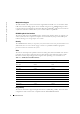
1 Product Overview Features and Benefits The 8-Port and 16-port Dell™ Console Switches integrate keyboard, video, and mouse (KVM) switching technology with advanced cable management, flexible access for up to two simultaneous users, and an intuitive user interface. The Console Switch features powerful on-screen management for easy system configuration and server selection.
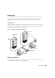
www.dell.com | support.dell.com Multiplatform Support The SIPs available with your Console Switch support PS/2 and USB server environments. PS/2, USB, Sun, and serial cabling options are also available using Avocent™ AVRIQ intelligent cables. Using the On-Screen Configuration and Activity Reporting (OSCAR ®) graphical user interface in conjunction with these modules allows you to switch easily across platforms.
FLASH Upgradable You can upgrade your firmware at any time through a simple update utility to ensure that your Console Switch system is always running the most current version available. Both the Console Switch and the SIPs are FLASH upgradable. See "Appendix A: Flash Upgrades" for more information. Tiering Expansion Each Console Switch supports up to 16 directly attached servers and can conveniently scale to support more.
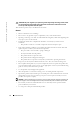
www.dell.com | support.dell.com CAUTION: The power supplies in your system may produce high voltages and energy hazards, which can cause bodily harm. Only trained service technicians are authorized to remove the covers and access any of the components inside the system. This document pertains only to the Dell Console Switch. General • Observe and follow service markings: • Do not service any product except as explained in your system documentation.
• To help prevent electric shock, plug the system and peripheral power cables into properly grounded electrical outlets. These cables are equipped with three-prong plugs to help ensure proper grounding. Do not use adapter plugs or remove the grounding prong from a cable. • Observe extension cable and power strip ratings. Make sure that the total ampere rating of all products plugged into the power strip does not exceed 80 percent of the ampere ratings limit for the power strip.
Product Overview www.dell.com | support.dell.
2 Installation Getting Started Before installing your Console Switch, refer to the following list to ensure you have all items that shipped with the appliance as well as other items necessary for proper installation.
www.dell.com | support.dell.com CAUTION: Before installing systems in a rack, install front and side stabilizers on stand-alone racks or the front stabilizer on racks joined to other racks. Failure to install stabilizers accordingly before installing systems in a rack could cause the rack to tip over, potentially resulting in bodily injury under certain circumstances. Therefore, always install the stabilizer(s) before installing components in the rack.
3 Line up the screw holes in the bracket with the screw holes in the switch. 4 With a Phillips screwdriver, fasten the front mounting brackets to the switch using two screws on each side. 5 Attach four cage nuts or clip nuts to the rack mounting flange of the rack cabinet’s front so that the nut is positioned on the inside of the rack. 6 Mount the switch assembly to the rack cabinet by matching the holes in the “short side” of each bracket to an appropriate set of matching holes on your rack cabinet.
www.dell.com | support.dell.com Figure 2-2. 1U Installation Installing the Console Switch Plug the supplied power cord into the back of the appliance and then into an appropriate power source. Figure 2-3 illustrates one possible configuration for your Console Switch. See the following detailed set of procedures to successfully install your appliance. CAUTION: To reduce the risk of electric shock or damage to your equipment: - Do not disable the power cord grounding plug.
Figure 2-3. Basic Console Switch Configuration Local User B (16-port model only) Configuration Port (for updating firmware) Console Switch Servers 2-16 Local User A Server 1 SIP To connect a SIP to each server: 1 Locate the SIPs for your Console Switch. 2 Attach the appropriately cable ends to the keyboard, monitor and mouse ports on the first server you will be connecting to the appliance.
www.dell.com | support.dell.com NOTE: When connecting a Sun AVRIQ module, you must use a multi-sync monitor to accommodate Sun computers that support both VGA and sync-on-green or composite sync. To connect local peripherals: 1 Select the keyboard, monitor and mouse to be connected to local user A. 2 Locate the port set labeled A on the back of the appliance. Connect these peripherals to their respective ports.
Figure 2-4.
www.dell.com | support.dell.com Adding Legacy Switches You can add legacy switches to the Console Switch system for easy integration into your existing configuration. In a tiered system, each ARI port will accommodate up to 24 servers. See the following table for legacy switches compatible with the Console Switch system. Table 2-1.
Figure 2-5. Console Switch Configuration with a Legacy KVM Switch Local User Console Switch SIP PS/2 or USB or AVRIQ PS/2, USB, Sun, or Serial SIP Legacy Switch Server 1 Legacy Switch Server 2 To add a legacy KVM switch: 1 Mount the KVM switch into your rack cabinet. Locate a length of CAT 5 cabling to connect between your Console Switch and the SIP for your switch. 2 Attach the keyboard, monitor and mouse connectors of the SIP to a user port on your tiered switch.
www.dell.com | support.dell.com 7 Repeat steps 2 to 5 for all tiered switches you wish to attach to your system. To connect local peripherals: 1 Select the keyboard, monitor and mouse to be connected to local user A. 2 Locate the port set labeled A on the back of the appliance. Connect these peripherals to their respective ports. NOTE: For the multiuser, 16-port Console Switch, repeat these steps for the local analog port set labeled B. 3 Bundle and label the cables for easy identification.
3 Basic Operation Controlling Your System at the Local User Ports The Console Switch features up to two local user port sets on the back of the unit that allow you to connect a monitor and a PS/2 keyboard and mouse for direct access. The 8-port Console Switch allows you to connect a single user, whereas the 16-port Console Switch allows you to connect two local users.
www.dell.com | support.dell.com Figure 3-1. Main Dialog Box NOTE: You can also press the key twice within one second to launch the OSCAR interface. You can use this key sequence in any place you see throughout this installer/user’s guide. Viewing the Status of Your Switch The status of the servers in your system is indicated in the right columns of the Main dialog box. The following table describes the status symbols. Table 3-1.
Table 3-1. OSCAR Interface Status Symbols (continued) Symbol Description SIP is being accessed by the indicated user channel (green channel letter). SIP is blocked by the indicated user channel (black channel letter). Selecting Servers Use the Main dialog box to select servers. When you select a server, the appliance reconfigures the keyboard and mouse to the correct settings for that server. To select servers: Double-click the server name, EID or port number.
www.dell.com | support.dell.com 2 Click Setup - Menu. The Menu dialog box appears. 3 Set a Screen Delay Time by typing the number of seconds of delay you want between being pressed and the Main dialog box displaying. 4 Click OK. To soft switch to a server: 1 To select a server, press . If the display order of your server list is by port (Port button is depressed), type the port number and press .
Table 3-2. OSCAR Interface Navigation Basics (continued) This Keystroke Does This Enter Completes a switch in the Main dialog box and exits the OSCAR interface. Performs the same function as the OK button. Print Screen, Backspace Toggles back to previous selection. Print Screen, Alt+0 Immediately disengages user from a server; no server is selected. Status flag displays Free. (This only applies to the <0> on the keyboard and not the keypad.
www.dell.com | support.dell.com Table 3-3. Setup Features to Manage Routine Tasks for Your Servers (continued) Feature Purpose Scan Set up a custom scan pattern for up to 16 servers. Security Set passwords to restrict server access. Enable the screen saver. Devices Identify the appropriate number of ports on an attached legacy switch. Names Identify servers by unique names. Switch Choose the switch mode and the share mode time-out.
Figure 3-3. Names Dialog Box NOTE: If the server list changes, the mouse cursor turns into an hourglass as the list is automatically updated. No mouse or keyboard input is accepted until the list update is complete. To assign names to servers: 1 In the Names dialog box, select a server name or port number and click Modify. The Name Modify dialog box displays. Figure 3-4. Name Modify Dialog Box 2 Type a name in the New Name box. Names of servers may be up to 15 characters long.
www.dell.com | support.dell.com 5 Click OK in the Names dialog box to save your changes. -orClick X or press to exit the dialog box without saving changes. NOTE: If a SIP has not been assigned a name, the EID is used as the default name. Assigning Device Types While the appliance automatically discovers legacy KVM switches, you will need to specify the number of ports on the legacy switch in the Devices dialog box.
Figure 3-6. Device Modify Dialog Box 3 Choose the number of ports supported by your legacy switch and click OK. 4 Repeat steps 1 to 3 for each port requiring a device type to be assigned. 5 Click OK in the Devices dialog box to save settings. NOTE: Changes made in the Device Modify dialog box are not saved until you click OK in the Devices dialog box. Changing the Display Behavior Use the Menu dialog box to change the display order of servers and set a Screen Delay Time for the OSCAR interface.
www.dell.com | support.dell.com Figure 3-7. Menu Dialog Box To choose the default display order of servers: 1 Select Name to display servers alphabetically by name. -orSelect EID to display servers numerically by EID number. -orSelect Port to display servers numerically by port number. 2 Click OK. To set a Screen Delay Time for the OSCAR interface: 1 Type in the number of seconds (0 to 9) to delay the OSCAR interface display after you press .
Table 3-4. OSCAR Status Flags (continued) Flag Description Flag indicating that the user has been disconnected from all systems Flag indicating that Broadcast mode is enabled To access the Flag dialog box: 1 Press . The Main dialog box appears. 2 Click Setup - Flag. The Flag dialog box appears. Figure 3-8. Flag Dialog Box To determine how the status flag is displayed: 1 Select Name or EID to determine what information will be displayed.
www.dell.com | support.dell.com Figure 3-9. Set Position Flag NOTE: Changes made to the flag position are not saved until you click OK in the Flag dialog box. 6 Click OK to save settings. -orClick X to exit without saving changes. Setting Console Security The OSCAR interface enables you to set security on your local user port console. You can establish a screen saver mode that engages after your console remains unused for a specified Inactivity Time.
2 Type the new password in the New text box and press . Passwords must contain both alpha and numeric characters, are case sensitive and may be up to 12 characters long. Legal characters are: A to Z, a to z, 0 to 9, space and hyphen. 3 In the Repeat box, type the password again and press . 4 Click OK to change only your password, and then close the dialog box. NOTE: If you should lose or forget your password, you must return your switch for service or technical support.
www.dell.com | support.dell.com 2 Select Enable Screen Saver. 3 Type the number of minutes for Inactivity Time (from 1 to 99) to delay activation of the screen saver. 4 Choose Energy if your monitor is ENERGY STAR® compliant; otherwise select Screen. CAUTION: Monitor damage can result from the use of Energy mode with monitors not compliant with ENERGY STAR®. 5 (Optional) Click Test to activate the screen saver test, which lasts 10 seconds then returns you to the Security dialog box. 6 Click OK.
Figure 3-11. 3 Click SIP to view individual SIP version information.The SIP Selection dialog box appears. Figure 3-12. 4 Version Dialog Box SIP Selection Dialog Box Select a SIP to view and click the Version button. The SIP Version dialog box appears. For more information on loading firmware, see "Appendix A: Flash Upgrades".
www.dell.com | support.dell.com Figure 3-13. 5 SIP Version Dialog Box Click X to close the SIP Version dialog box. Resetting a SIP PS/2 SIPs can be reset using the Reset button in the SIP Version dialog box. NOTE: This procedure is only relevant where your Console Switch system involves a PS/2 SIP attached to a tiered switch. On these occasions, it may be necessary to reset the SIP when the tiered switch is not recognized.
Figure 3-14. SIP Version Dialog Box 5 Click Reset. A warning message appears, warning that the function is for tiered switches only and that resetting the SIP could result in the need to reboot the target server. 6 Click OK to proceed with the reset. or 7 Press to exit. Resetting Your Keyboard and Mouse If a keyboard or mouse locks up, you may be able to re-establish operation of these peripherals by issuing a reset command. To reset the mouse and keyboard values: 1 Press .
www.dell.com | support.dell.com Figure 3-15. Commands Dialog Box Scanning Your System In scan mode, the appliance automatically scans from port to port (server to server). You can scan up to 16 servers, specifying which servers to scan and the number of seconds that each server will display. The scanning order is determined by the order in which the servers are added to the Scan list. The list is always shown in scanning order.
Figure 3-16. Scan Dialog Box 3 The dialog box contains a listing of all servers attached to your appliance. Click the check box next to the servers you wish to scan. -orDouble-click on a server’s name or port. -orPress and the number of the server you wish to scan. You can select up to 16 servers from the entire list. 4 In the Scan Time box, type the number of seconds (from 3 to 99) of desired time before the scan moves to the next server in the sequence. 5 Click OK.
www.dell.com | support.dell.com Figure 3-17. Commands Dialog Box 3 Select Scan Enable in the Commands dialog box. 4 Click X to close the Commands dialog box. NOTE: Scanning will begin when the Main dialog box or flag is displayed. Scanning is inhibited in any other OSCAR dialog box. To cancel scan mode: 1 Select a server if the OSCAR interface is open. -orMove the mouse or press any key on the keyboard if the OSCAR interface is not open. Scanning will stop at the currently selected server.
Figure 3-18. Diagnostics Dialog Box NOTE: A SIP may appear to be offline while it is being upgraded. Next to each item to be tested, you will see a pass (green circle) or fail (red x) symbol display to the left of each item as that test finishes. The following table details each of the tests. Table 3-5.
www.dell.com | support.dell.com Figure 3-19. Diagnostics Warning Message Box 3 Click OK to begin diagnostics. -orClick X or press to exit the dialog box without running a diagnostic test. 4 All users are disconnected and the Diagnostics dialog box displays. 5 As each test is finished, a pass (green circle) or fail (red x) symbol appears. The test is complete when the last test’s symbol displays.
Figure 3-20. Broadcast Dialog Box NOTE: Broadcasting Keystrokes - The keyboard state must be identical for all servers receiving a broadcast to interpret keystrokes identically. Specifically, the and modes must be the same on all keyboards. While the appliance attempts to send keystrokes to the selected servers simultaneously, some servers may inhibit and thereby delay the transmission.
www.dell.com | support.dell.com Figure 3-21. Broadcast Enable Dialog Box 5 Click OK to enable the broadcast. Click X or press Escape to cancel and return to the Commands dialog box. 6 If broadcasting is enabled, type the information and/or perform the mouse movements you want to broadcast from the user station. Only servers in the list are accessible. NOTE: The other user (16-port switch only) is disabled when broadcast mode is enabled.
Figure 3-22. 3 Switch Dialog Box Select either Preemptive or Cooperative as your switch mode.
Basic Operation www.dell.com | support.dell.
4 Appendices Appendix A: Flash Upgrades Upgrading the Console Switch You can upgrade the firmware of your Console Switch by using a special update utility provided by Dell. This utility automatically configures the port communications settings to allow direct downloading from the connected server.
www.dell.com | support.dell.com Possible Error Conditions If the download does not execute properly, verify the following: • Verify that the COM port is correct. • Verify that no other program is currently using the COM port, or that a previous DOS window/shell is open that had used the desired COM port. • Verify that no other copies of the WUpDate utility are currently running. • Verify that a serial cable is used.
Upgrading the SIP The Server Interface Pods (SIPs) can be upgraded individually or simultaneously. NOTICE: Do not cycle power to the server or disconnect the SIP during this process. A loss of power will render the SIP inoperable and require the unit be returned to the factory for repair. To simultaneously upgrade multiple SIPs: 1 Press . The Main dialog box appears. 2 Click Commands-SIP Status. The SIP Status dialog box appears. Figure 4-1.
www.dell.com | support.dell.com To upgrade SIP firmware individually: 1 Press . The Main dialog box appears. 2 Click Commands-Display Versions. The Version dialog box appears. Figure 4-3. 3 Click SIP to view individual SIP version information. Figure 4-4. 4 52 Version Dialog Box SIP Selection Dialog Box Select the SIP that you wish to upgrade and click the Version button. The SIP Version dialog box appears.
Figure 4-5. 5 Click the Load Firmware button. The SIP Load dialog box appears. Figure 4-6. 6 SIP Version Dialog Box SIP Load Dialog Box Click OK to initiate the upgrade and return to the SIP Status dialog box. NOTE: During an upgrade, the SIP status indicator in the Main dialog box will be yellow. The SIP is unavailable while an upgrade is in progress. When an upgrade is initiated, any current connection to the server via the SIP will be terminated.
www.dell.com | support.dell.com Appendix B: Technical Specifications Table 4-1.
Table 4-1.
www.dell.com | support.dell.com Appendix C: Notifications USA Notification CAUTION: Changes or modifications to this unit not expressly approved by the party responsible for compliance could void the user's authority to operate the equipment. NOTE: This equipment has been tested and found to comply with the limits for a Class A digital device, pursuant to Part 15 of the FCC Rules.
Agency Approvals UL/cUL (UL 60950/CSA 22.2 No. 60950:2000) ICES-003 NOM-019-SCFI-1993 IRAM S Mark (Resolution 92/98) ACA AS/NZS 55022, class A CNS 13438 FCC Class A, EN60950:2000, EN55022:1998, EN55024:1998, EN61000-3-3:1995 +A1,A2.
Appendices www.dell.com | support.dell.
Index A E P ACI, 18 EID, 23, 25, 33 Analog Console Interface, See ACI Electronic ID, See EID Password Changing, 35 Removing, 36 Analog Rack Interface, See ARI Energy, 35 ARI, 7, 18, 20, 28, 30 F AVRIQ, 8 Sun, 18 Firmware Upgrading, 49 B Broadcasting, 44 D Device types Assigning, 30 Display behavior Changing, 31 Rack Mounting, 13 Firmware CRCs, 43 S FLASH Upgrade, 9 Scan list, 40 Flash Upgrading, 49 C Comm Interfaces Checking, 43 R Scan mode, 41 Cancelling, 42 Scanning, 40 Screen Dela
Index Status flag Controlling, 33 Positioning, 34 Switch status, 24 System Diagnostics Running, 42 T Tiering, 9, 18 V Version Information Displaying, 37 60 Index