Stacking Dell PowerConnect 10G Switches: M8024-k, 8024, 8024F Victor Teeter
Stacking PowerConnect 10G Switches: M8024-k, 8024, 8024F This document is for informational purposes only and may contain typographical errors and technical inaccuracies. The content is provided as is, without express or implied warranties of any kind. © 2011 Dell Inc. All rights reserved. Dell and its affiliates cannot be responsible for errors or omissions in typography or photography. Dell, the Dell logo, and PowerEdge are trademarks of Dell Inc.
Stacking PowerConnect 10G Switches: M8024-k, 8024, 8024F Contents Contents .................................................................................................................... 1 Introduction ................................................................................................................ 3 Stacking and Management .......................................................................................... 4 Stacking and Redundancy ................................................
Stacking PowerConnect 10G Switches: M8024-k, 8024, 8024F Appendix B - Network Switch Versions .............................................................................. 61 About Dell .............................................................................................................. 61 Figures Figure 1. Dell PowerConnect M8024-k Switch (10G Ethernet) ................................................. 3 Figure 2. Dell PowerConnect 8024 (10G Ethernet) ........................................
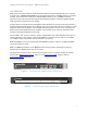
Stacking PowerConnect 10G Switches: M8024-k, 8024, 8024F Introduction Many Dell PowerConnect switches include a stacking feature that allows multiple switches to operate as a single unit. Starting with firmware 4.2, the latest PowerConnect 10 Gigabit switches can now be stacked. These stacks can include up to six 8024/8024F switches or up to six M8024-k switches. Appendix A at the end of this document shows the maximum scalability, stacking six 8024F switches using eight stack ports between each member.
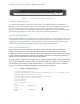
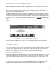
Stacking PowerConnect 10G Switches: M8024-k, 8024, 8024F LNK/ SPD LNK/ SPD ACT ACT 1 2 3 4 5 6 7 8 9 Figure 3. 10 11 12 13 14 15 16 17 18 19 20 21 22 23 24 Combo 21 22 23 24 Dell PowerConnect 8024F (10G Ethernet) Stacking and Management An important advantage of stacking is that it provides a consolidated interface for management of multiple switches linked together.
Stacking PowerConnect 10G Switches: M8024-k, 8024, 8024F Notice there is only one member line in the configuration. If there were three members in the stack then there would be three member lines in the configuration, such as stack member 1 1 member 2 1 member 3 1 ! PCM8024-k ! PCM8024-k ! PCM8024-k Note: A single “stack member” configuration is always present on stack-capable switches even if they are not part of an actual stack. The single switch is considered a “stack of one”.
Stacking PowerConnect 10G Switches: M8024-k, 8024, 8024F SW --1 2 3 Management Status ---------Mgmt Sw Stack Mbr Stack Mbr Standby Preconfig Status Model ID --------- ------------PC8024 PC8024F Oper Stby PC8024 Plugged-in Model ID ------------PC8024 PC8024F PC8024 Switch Status ------OK OK OK Note that in this example Unit 1 is the Master (Mgmt Sw) and Unit 3 is the Standby (Oper Stby) ready to take over as Master in the event the Master fails.
Stacking PowerConnect 10G Switches: M8024-k, 8024, 8024F If the unit number is configured and there are no other devices using the unit number, then the switch starts using the configured unit number. If the switch detects that the maximum number of units already exist in the stack making it unable to assign a unit number, then the switch sets its unit number to unassigned and does not participate in the stack.
Stacking PowerConnect 10G Switches: M8024-k, 8024, 8024F Note: If Simple Mode is enabled it will need to be disabled prior to using this document. Consult the User Guide for more information on Simple Mode, and how to disable it. Note: Any stack configuration should be removed prior to downgrading firmware to version 4.1.x.x or earlier, in the event a downgrade is desired.
Stacking PowerConnect 10G Switches: M8024-k, 8024, 8024F Just like the PowerConnect 1G modular switches (M6220 and M6348), the M8024-k supports stacking across multiple M1000e chassis. That means it is possible to have six M1000e chassis’, each one having an M8024-k installed and all six M8024-k switches be members of the same stack. The following scenarios show steps to create a stack.
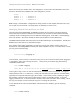
CMC2 2 3 4 5 7 8 1 A1 B1 2 3 4 6 9 5 C2 B2 2 3 17 4 2 19 18 4 4 1 3 3 17 17 4 3 17 CONSOLE CONSOLE 4 3 17 CONSOLE CONSOLE Figure 6.
Stacking PowerConnect 10G Switches: M8024-k, 8024, 8024F redirect, see the Dell Blade Server CMC User's Guide at http://support.dell.com/support/edocs/software/smdrac3/cmc/index.htm. Any SFP+ port, whether built-in to the M8024-k or on an expansion module, may be used for stacking. For this example the built-in ports 17 and 18 are used as shown in Figure 5. For each switch in the stack, one cable from a stacking port on a switch is connected to a stacking port on the next switch.
Stacking PowerConnect 10G Switches: M8024-k, 8024, 8024F 1 1 1 1 1 0/20 1/1 1/2 1/3 1/4 Ethernet Ethernet Ethernet Ethernet Ethernet Ethernet Ethernet Ethernet Ethernet Ethernet Link Down Not Created Not Created Not Created Not Created 10 Unknown Unknown Unknown Unknown This command provides four pieces of information used for stacking. It shows the Unit number for the switch which is used in the stacking commands in the examples below.
Stacking PowerConnect 10G Switches: M8024-k, 8024, 8024F console(config)#boot auto-copy-sw console(config)#no boot auto-copy-sw allow-downgrade console(config)#do show auto-copy-sw Stack Firmware Synchronization Synchronization................................ Enabled SNMP Trap status............................... Enabled allow-downgrade................................ Disabled Save the configuration to the Startup-Configuration.
Stacking PowerConnect 10G Switches: M8024-k, 8024, 8024F Note: The running-configuration doesn’t need to be copied to the startup-configuration in order to create the stack on the next reload. When the stacking commands above were added to the runningconfiguration they were also added to the meta-data (see meta-data considerations above) and will be utilized from that location upon reload.
Stacking PowerConnect 10G Switches: M8024-k, 8024, 8024F 1 1 1 2 2 2 2 2 2 2 2 3 3 3 3 3 3 3 3 1/2 1/3 1/4 0/17 0/18 0/19 0/20 1/1 1/2 1/3 1/4 0/17 0/18 0/19 0/20 1/1 1/2 1/3 1/4 Ethernet Ethernet Ethernet Stack Stack Ethernet Ethernet Ethernet Ethernet Ethernet Ethernet Stack Stack Ethernet Ethernet Ethernet Ethernet Ethernet Ethernet Ethernet Ethernet Ethernet Stack Stack Ethernet Ethernet Ethernet Ethernet Ethernet Ethernet Stack Stack Ethernet Ethernet Ethernet Ethernet Ethernet Ethernet Not Create
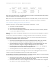
Stacking PowerConnect 10G Switches: M8024-k, 8024, 8024F Figure 7. CMC Login Screen for the M1000e 2. Enter the username and password. The factory default username is root and the default password is calvin. 3. From the CMC web page, select I/O Module Overview to see all M8024-k switches installed in the M1000e chassis. (Figure below) All stand-alone switches in the chassis will show up as Master. In this example, there are three stand-alone switches in the chassis that can be stacked together.
Stacking PowerConnect 10G Switches: M8024-k, 8024, 8024F Figure 8. I/O Module Status screen (CMC) 4. Launch the Web UI of the switch to be the Master by clicking the Launch IOM GUI button or directly through a web browser by typing the IP address into the URL field. Either method will bring up the login page.
Stacking PowerConnect 10G Switches: M8024-k, 8024, 8024F 5. After login, the first screen to appear will be the Home screen which shows ports 17 thru 20 are available for stacking. The current stacking member number is also displayed on this screen. Before stacking, all single membersl have the Stack number of 1. 6. Click System > Stack Management > Stack Port Summary to bring up the next page used to select the ports for stacking. For this example ports 17 and 18 are used. 7.
Stacking PowerConnect 10G Switches: M8024-k, 8024, 8024F 9. Select System > Stack Management > Unit Configuration. Note: The next three steps are optional, but allow the user to select the Switch ID for each member. A stack will be created even if these settings are skipped. Settings can also be changed after the stack is created. 10. Select the Switch ID for this switch.
Stacking PowerConnect 10G Switches: M8024-k, 8024, 8024F 12. Click Apply. Changing a Switch ID requires a reboot of the stack. Be sure to save the configuration before allowing the reboot. This can be done from the System > File Management > Copy Files screen as described on the next page. Note: After changing a Switch ID and reloading the switch, the old ID remains in the configuration until removed.
Stacking PowerConnect 10G Switches: M8024-k, 8024, 8024F 15. Click Apply. The next screen will save the configuration to the Startup Configuration. 16. Select System > File Management > Copy Files from the main navigation menu. 17. Select the Copy Configuration option, using a Source of Running Config, and a Destination of Startup Config. 18. Click Apply. 19. Repeat each step above for all other member units to be added to the stack before cabling any stack ports together.
Stacking PowerConnect 10G Switches: M8024-k, 8024, 8024F 20. Once every switch in the stack has been configured, power down (unplug) all M8024-k switches that will be joining the stack. 21. Cable together two switches stack ports using a single cable. When the stack is first created, the switch with the highest MAC address will become master. 22. Power up the two M8024-k switches by inserting them back into the M1000e blade chassis slots.
Stacking PowerConnect 10G Switches: M8024-k, 8024, 8024F Note: It is simple to change the Master or Standby to a different unit if desired using the Unit Configuration screen. Configuring the 8024/8024F Stack PowerConnect 8024/8024F switches can be stacked up to six high, supporting up to 132 front-panel ports when two ports on each unit are configured as stacking ports.
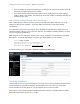
Stacking PowerConnect 10G Switches: M8024-k, 8024, 8024F LNK/ SPD ACT 1 2 3 4 5 6 7 8 9 10 11 12 13 14 15 16 17 18 19 20 21 22 23 24 LNK/ SPD Combo ACT 21 22 23 24 LNK/ SPD LNK/ SPD ACT ACT 1 2 3 4 5 6 7 8 9 10 11 12 13 14 15 16 17 18 19 20 21 22 23 24 LNK/ SPD Combo ACT 1 2 3 4 5 6 7 Figure 10.
Stacking PowerConnect 10G Switches: M8024-k, 8024, 8024F Notice that the Configured Stack Mode and the Running Stack Mode are both Ethernet. Perform the following commands.
Stacking PowerConnect 10G Switches: M8024-k, 8024, 8024F Continue cabling the remaining switches using one cable per switch until all are added. After each is cable, power up that switch. These can be done quickly and do not require any wait time between cabling and powering up, or waiting between adding each member. After all members are added, go ahead and install the final cable between the first and last members to create a ring or loop.
Stacking PowerConnect 10G Switches: M8024-k, 8024, 8024F 2 2 2 2 2 2 2 2 2 2 2 2 2 2 2 2 2 2 2 3 3 3 3 0/06 0/07 0/08 0/09 0/10 0/11 0/12 0/13 0/14 0/15 0/16 0/17 0/18 0/19 0/20 0/21 0/22 0/23 0/24 0/21 0/22 0/23 0/24 Ethernet Ethernet Ethernet Ethernet Ethernet Ethernet Ethernet Ethernet Ethernet Ethernet Ethernet Ethernet Ethernet Ethernet Ethernet Stack Stack Ethernet Ethernet Stack Stack Ethernet Ethernet Ethernet Ethernet Ethernet Ethernet Ethernet Ethernet Ethernet Ethernet Ethernet Ethernet Ether
Stacking PowerConnect 10G Switches: M8024-k, 8024, 8024F 1. After login, the first screen to appear will be the Home screen which shows the current stacking member number. Before stacking, the single member will have the Stack number of 2. Click System > Stack Management > Stack Port Summary to bring up the next page used to select the ports for stacking. For this example ports 21 and 22 are used. 3. Clicking the box in the Edit column activates the pull-down menu in the Configured Stackmode column.
Stacking PowerConnect 10G Switches: M8024-k, 8024, 8024F Note: Since this example uses a PowerConnect 8024, there are only four possible ports that can be stacked. A PowerConnect 8024F would have 24 ports that could be used for stacking. 4. Click Apply. If the message below appears, click Close. The switch will not reboot until the reload command is given. 5. Select System > Stack Management > Unit Configuration.
Stacking PowerConnect 10G Switches: M8024-k, 8024, 8024F Select the Unit Type of Management, Stand-by, or Member. For this example, Management will be selected for all switches since they are all currently stand-alone. Once a stack is created, this setting will allow each stack member to be individually selected for these roles. Note: After a stack is created, any member of the stack can be made the Master using this screen.
Stacking PowerConnect 10G Switches: M8024-k, 8024, 8024F 10. Optionally, enable an SNMP Trap to be sent whenever a firmware sync is triggered; also if desired, enable the Master to downgrade a new member unit even if the new unit has a more recent firmware revision. Note: Make sure you are making the following change on the switch that will become Master, which is the switch with the highest MAC address during stack creation.
Stacking PowerConnect 10G Switches: M8024-k, 8024, 8024F 14. Click Apply. 15. Once all systems have been configured with stacking ports, power down all switches. 16. Cable any two switches together using a single cable between the two. 17. Power up the switches that are cabled together. When the stack is first created, the switch with the highest MAC address will become master. Allow several minutes for this stack of 2 devices to come up completely.
Stacking PowerConnect 10G Switches: M8024-k, 8024, 8024F Stack Member units serial ports and management IP addresses are no longer accessible for managing those devices. The Master’s management ports are required to monitor and configure every port in the stack. Validation To see the new stack, login to the Master’s Web UI. Select System > Stack Management > Stack Summary. Note: Remember, it is simple to change the Master or Standby to a different unit if desired using the Unit Configuration screen.
Stacking PowerConnect 10G Switches: M8024-k, 8024, 8024F Note: If the unit has never been a member of a stack, the Unit number displayed will be 1 as shown above. If previously a stack member, the Unit number displayed can be anywhere between 1 and 6.
Stacking PowerConnect 10G Switches: M8024-k, 8024, 8024F Configuration Saved! One additional cable is required for each switch being added to the stack. Power down the new stack member to be added. Note: To power down an 8024/8024F, simply remove the power cords from the back of the device. To power down an M8024-k, unplug it from the M1000e blade chassis. Plug the new cable into one of the two stack ports on the new switch unit to be added. See Figure 11.
Stacking PowerConnect 10G Switches: M8024-k, 8024, 8024F LNK/ SPD ACT 1 2 3 4 5 6 7 8 9 10 11 12 13 14 15 16 17 18 19 20 21 22 23 24 1 2 3 4 5 6 7 8 9 10 11 12 13 14 15 16 17 18 19 20 21 22 23 24 LNK/ SPD Combo ACT LNK/ SPD 2 3 4 5 6 7 8 9 10 11 12 13 14 15 16 17 18 19 20 21 22 23 24 ACT 21 22 23 24 21 22 23 24 21 22 23 24 21 22 23 24 LNK/ SPD Combo ACT 1 LNK/ SPD ACT LNK/ SPD Combo ACT New member unit ad
Stacking PowerConnect 10G Switches: M8024-k, 8024, 8024F members are to be added, follow these directions and complete the install of one before going to the next. Complete these steps again for each remaining switch to be added. The example given below allows the user to add the new member without preconfiguring the existing stack, though the new member itself will need to be configured.
Stacking PowerConnect 10G Switches: M8024-k, 8024, 8024F 6. Click Apply. In order for the new member unit to work properly within a stack, it needs to have the same firmware as the Master. The easiest way to accomplish this is to configure the Master switch to use the Stack Firmware Synchronization feature shown below. Optionally, a manual update of the firmware can be performed on the new member to synchronize the firmware prior to adding it to the stack.
Stacking PowerConnect 10G Switches: M8024-k, 8024, 8024F This setting automatically upgrades firmware on new members as they are added to the stack. In the event the new stack member has a newer firmware version, a downgrade will also be allowed. 9. To prevent the downgrade of the new stack member unit’s firmware, set the Allow Downgrade to Disable and click Apply. One additional cable is required for each switch being added to the stack. 10.
Stacking PowerConnect 10G Switches: M8024-k, 8024, 8024F LNK/ SPD ACT 1 2 3 4 5 6 7 8 9 10 11 12 13 14 15 16 17 18 19 20 21 22 23 24 1 2 3 4 5 6 7 8 9 10 11 12 13 14 15 16 17 18 19 20 21 22 23 24 LNK/ SPD Combo ACT LNK/ SPD 2 3 4 5 6 7 8 9 10 11 12 13 14 15 16 17 18 19 20 21 22 23 24 ACT 21 22 23 24 21 22 23 24 21 22 23 24 21 22 23 24 LNK/ SPD Combo ACT 1 LNK/ SPD ACT LNK/ SPD Combo ACT Member unit to be
Stacking PowerConnect 10G Switches: M8024-k, 8024, 8024F 12. Power up the new member switch by restoring the power cables (on 8024/8024F) or plugging it into the blade chassis (on the M8024-k). It usually takes a few minutes for the stack to build and restart. Once restarted and the new member has joined the stack, the remaining configuration can be set on including VLANs, LAGs, data cables to other equipment, etc. To verify the new stack member has been added, login to the Master’s Web UI.
Stacking PowerConnect 10G Switches: M8024-k, 8024, 8024F Command-Line Interface Method To find the firmware versions the stack members are using, enter the following. console#show version Image Descriptions image1 : default image image2 : Images currently available on Flash unit image1 image2 current-active next-active ----- ------------ ------------ ----------------- ----------------1 4.2.0.1 4.2.0.0 image1 image1 2 4.2.0.1 4.2.0.0 image1 image1 3 4.2.0.0 4.2.0.1 image2 image2 4 4.2.0.1 4.2.0.
Stacking PowerConnect 10G Switches: M8024-k, 8024, 8024F unit ----1 2 3 4 image1 -----------4.2.0.1 4.2.0.1 4.2.0.2 4.2.0.1 image2 -----------4.2.0.2 4.2.0.2 4.2.0.1 4.2.0.2 current-active next-active ----------------- ----------------image1 image1 image1 image1 image2 image2 image1 image1 The current-active column now shows the same values as the next-active column. The next step is to activate the image that contains the new firmware.
Stacking PowerConnect 10G Switches: M8024-k, 8024, 8024F To validate, login to the stack Master and perform a show version command. For the example given the following is displayed. console#show version Images currently available on Flash unit image1 image2 current-active next-active ----- ------------ ------------ ----------------- ----------------1 4.2.0.1 4.2.0.2 image2 image2 2 4.2.0.1 4.2.0.2 image2 image2 3 4.2.0.2 4.2.0.1 image1 image1 4 4.2.0.1 4.2.0.
Stacking PowerConnect 10G Switches: M8024-k, 8024, 8024F TFTP server. The stack will need access to the TFTP server on the network and the firmware file will need to be present in the download folder of the TFTP server. Perform the following: 4. Select System > File Management > File Download. 5. Select Firmware for the File Type, and TFTP for the Transfer Mode. 6. Enter the IP address of the TFTP server into the Server Address field, and enter the name of the Firmware file into the Source File Name field.
Stacking PowerConnect 10G Switches: M8024-k, 8024, 8024F 9. Click Close. After a firmware file is copied from a TFTP server to the Master, it begins automatically distributing it to all member units in the stack. This procedure usually takes a few minutes longer than updating a single, non-stacked switch. 10. Select System > File Management > Active Images. 11. Notice the firmware (i.e. 4.2.0.4) was copied into the inactive image for each member. 12.
Stacking PowerConnect 10G Switches: M8024-k, 8024, 8024F 16. Click Apply. 17. After the stack resets, verify the new firmware has become active. 18. Select System > File Management > Active Images again. 19. Notice the new firmware (i.e. 4.2.0.4) is now the Current-Active image for each member.
Stacking PowerConnect 10G Switches: M8024-k, 8024, 8024F on the failed unit, the stack will be intact without changes. The example below demonstrates how to manually remove a single member while keeping the stack intact. Command-Line Interface Method Since any SFP+ interface on these switches can be used for stacking, be sure to verify exactly which ports are being used so they are un-cabled and re-routed last. This information is found with the following command.
Stacking PowerConnect 10G Switches: M8024-k, 8024, 8024F Note: An M8024-k modular blade switch does have a blue LED identifier for its Master only. An easy way to find the Unit number and identify order of the stacked units is to use logging commands. From the Telnet or Serial port CLI, perform the following. console(config)#logging on From the stack, create a link-up or link-down on any port for two to three seconds by either plugging in or unplugging a cable, then reversing the action.
Stacking PowerConnect 10G Switches: M8024-k, 8024, 8024F Do not remove or re-route stacking cables until prompted in the last step below. Disconnect all other links on the stack member to be removed and re-route the traffic that was going through this unit so it now goes through the ports that were prepared on the remaining stack unit members. Only after re-routing the traffic through the remaining stack units, remove both stacking cables from the switch to be removed.
Stacking PowerConnect 10G Switches: M8024-k, 8024, 8024F Removing Units from the Stack Configuration Once a stack unit has been removed, it may be desirable to remove it completely from the stack configuration. Issuing a no member command in Stack Configuration mode will delete the removed switch from the configured stack information. For this example Unit #3 (Standby) will be removed. Assume that the bottom Unit in Figure 16 is Unit #3.
Stacking PowerConnect 10G Switches: M8024-k, 8024, 8024F console(config)#switch 4 renumber 3 The switch will be reset to perform unit renumbering and the configuration of switch interfaces will be cleared. Are you sure you want to renumber? (y/n)y Allow a few minutes for the switch to renumber, then enter the following.
Stacking PowerConnect 10G Switches: M8024-k, 8024, 8024F 2. Look for all interfaces shown to be in Stack mode. Note the Interfaces used for stacking for each Stack Unit. This information will be needed in the last step below when re-routing the stack cables. Note: If the member unit is being removed due to malfunctioning, dead switch, or is not responding to commands, information from the remaining switches can be used to find the stack interfaces.
Stacking PowerConnect 10G Switches: M8024-k, 8024, 8024F 2. Click Apply. 3. From the stack, create a link-up or link-down on any port for two to three seconds by either plugging in or unplugging a cable, then reversing the action. For this example, port 17 is used on one of the three stack members. 4. Select System > Logs > RAM Log. Check the log for a Link Down trap for port 17. The log will identify both the Unit and Port that was used in the link operation.
Stacking PowerConnect 10G Switches: M8024-k, 8024, 8024F 5. Continue this process to identify all Unit numbers in the switch. Note: If the show logging command is full, it can be saved off to another location then cleared for easier reading. Also if the log is not needed, it can be cleared as well prior to creating the link events. 6. To now identify which unit is the stack Master and which ones are members, go to System > Stack Management > Stack Summary.
Stacking PowerConnect 10G Switches: M8024-k, 8024, 8024F LNK/ SPD ACT 1 2 3 4 5 6 7 8 9 10 11 12 13 14 15 16 17 18 19 20 21 22 23 24 1 2 3 4 5 6 7 8 9 10 11 12 13 14 15 16 17 18 19 20 21 22 23 24 LNK/ SPD Combo ACT LNK/ SPD 2 3 4 5 6 7 8 9 10 11 12 13 14 15 16 17 18 19 20 21 22 23 24 ACT 21 22 23 24 21 22 23 24 21 22 23 24 21 22 23 24 LNK/ SPD Combo ACT 1 LNK/ SPD ACT LNK/ SPD Combo ACT Member unit to be
Stacking PowerConnect 10G Switches: M8024-k, 8024, 8024F Notice that Unit #4 is no longer present, and its Management Status is Unassigned. 1. To remove it completely from the stack configuration, select System > Stack Management > User Configuration. 2. Select the switch ID of the switch that was removed (i.e. 4). 3. Place a check in the Remove Switch box at the bottom of the screen. 4. Click Apply. 5.
Stacking PowerConnect 10G Switches: M8024-k, 8024, 8024F Renumbering Stack Units PowerConnect 8024/8024F/M8024-k switch Stacks allow users to renumber the Units in the stack. For example: a physical port in a stack is Te4/0/21, where 4 is the Unit Number. If this Stack is renumbered so that Unit 4 is now Unit 2, then the same physical port that was Te4/0/21 is now Te2/0/21. Renumbering a Stack so there are no breaks in the numbering sequence, or renumbering for any other reason, is optional.
Stacking PowerConnect 10G Switches: M8024-k, 8024, 8024F 3. Select System > Stack Management > Unit Configuration. 4. In the Switch ID field select 4 from the pull-down menu, and enter a 3 in the Change Switch ID to field. 5. Click Apply. Renumbering requires a reset of the switch and will clear the configuration of the interfaces on the switch receiving the new Unit number. The resulting dialog box appears to warn the user. 6. Click OK if you agree. 7.
Stacking PowerConnect 10G Switches: M8024-k, 8024, 8024F Notice also that the old number still exists but is Unassigned. To permanently remove this Unassigned number, follow the instructions in this guide under Removing Units from the Stack Configuration Consult the User Guide for additional stacking information.
Stacking PowerConnect 10G Switches: M8024-k, 8024, 8024F Appendix A – Maximum Stacking Scalability LNK/ SPD LNK/ SPD ACT ACT 1 2 3 4 5 6 7 8 9 10 11 12 13 14 15 16 17 18 19 20 21 22 23 24 Combo 21 22 23 24 LNK/ SPD LNK/ SPD ACT ACT 1 2 3 4 5 6 7 8 9 10 11 12 13 14 15 16 17 18 19 20 21 22 23 24 Combo 21 22 23 24 LNK/ SPD LNK/ SPD ACT ACT 1 2 3 4 5 6 7 8 9 10 11 12 13 14 15 16 17 18 19 20 21 22 23 24 Combo 21 22