
System information

Stacking PowerConnect 10G Switches: M8024-k, 8024, 8024F
2
Appendix B - Network Switch Versions .............................................................................. 61
About Dell .............................................................................................................. 61
Figures
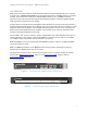
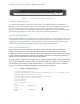
Figure 1. Dell PowerConnect M8024-k Switch (10G Ethernet) ................................................. 3
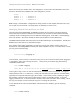
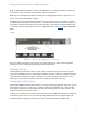
Figure 2. Dell PowerConnect 8024 (10G Ethernet) .............................................................. 3
Figure 3. Dell PowerConnect 8024F (10G Ethernet) ............................................................ 4
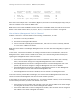
Figure 4. SFP+ Four Port Expansion for the M8024-k ............................................................ 8
Figure 5. Stacking multiple M8024-k switches in a single M1000e........................................... 10
Figure 6. Stacking M8024-k switches across multiple M1000e chassis ...................................... 10
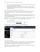
Figure 7. CMC Login Screen for the M1000e ..................................................................... 16
Figure 8. I/O Module Status screen (CMC) ....................................................................... 17
Figure 9. Stacking 8024/8024F switches using a single stack link ........................................... 23
Figure 10. Stacking 8024/8024F switches using multiple stack links ......................................... 24
Figure 11. Preparing a Stack Unit (CLI method) ................................................................. 35
Figure 12. New Stack Unit Added (CLI method) .................................................................. 36
Figure 13. Preparing a Stack Unit (Web UI method) ............................................................ 40
Figure 14. New Stack Unit Added (Web UI method) ............................................................. 40
Figure 15. Cabling of four stacked units .......................................................................... 50
Figure 16. Removal of a stack unit ................................................................................. 50
Figure 17. Cabling of four stacked units .......................................................................... 56
Figure 18. Removal of a stack unit ................................................................................. 56
Tables
Table 1. Switch Firmware Versions .............................................................................. 61