Dell Networking Installation Guide for the Z9500 Switch
Notes, Cautions, and Warnings NOTE: A NOTE indicates important information that helps you make better use of your computer. CAUTION: A CAUTION indicates either potential damage to hardware or loss of data and tells you how to avoid the problem. WARNING: A WARNING indicates a potential for property damage, personal injury, or death. Copyright © 2014 Dell Inc. All rights reserved. This product is protected by U.S. and international copyright and intellectual property laws.
Contents 1 About this Guide....................................................................................................5 Related Publications.............................................................................................................................. 5 2 Introduction...........................................................................................................6 Product Description...........................................................................................
Splitting QSFP+ Ports to SFP+ Ports.................................................................................................. 33 Important Points to Remember....................................................................................................34 Supplying Power and Powering Up the System................................................................................ 34 AC Power..............................................................................................................
About this Guide 1 This guide provides site preparation recommendations, and step-by-step procedures for rack mounting, installing modules, and connecting to a power source. After you have completed the hardware installation and power-up of the Z9500, for software configuration information, refer to the Dell Networking Configuration Guide for the Z9500 Switch and for Command Line Interface (CLI) information, refer to the Dell Networking Command Line Reference Guide for the Z9500 Switch.
2 Introduction This document provides basic information about installing the Z9500 switch. For information about how to configure and monitor switch features, refer to the Dell Networking Configuration Guide for the Z9500 Switch, which is available on the Dell Support website at http:// support.dell.com/manuals.
Unpacking the Switch 3 The switch and its accessories are shipped in a single box. The power cords may be shipped in a separate box. Before unpacking the switch, inspect the container and immediately report any evidence of damage. Verify that you have received your ordered items, including the following: WARNING: If any item is missing or damaged, contact your Dell Networking representative or reseller for instructions.
6. Installing Fan Modules 7. Securing Power Cables 8. Installing the QSFP+ Optics 9. Installing the Cable Management System 10.
Hardware Overview 4 This section contains information about device characteristics and modular hardware configurations for the Z9500. The Z9500 has the following physical dimensions: • Height: 5.2 inches (132.08 mm) • Width: 17.4 inches (441.96 mm) • Depth: 32 inches (812.80 mm) The Z9500 has a chassis design with 5280Gbps switching bandwidth. The system also provides one DB9 RS-232 console port with YOST RJ-45 pinout and a dedicated Ethernet service port for out-of-band (OOB) management functions.
Utility Panel The Utility panel side of the platform contains the fan and power modules. Figure 2. Utility Side 1. Fan Trays 2. Power Supplies Power Supplies The Z9500 supports four hot-swappable Power supply units (PSUs) . NOTE: The PSUs must be installed at the customer site. PSUs are field replaceable. To ensure power redundancy and adequate cooling, install four power supplies in the switch.
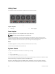
The following table lists the LED definitions for the Z9500 system. Figure 3. System LED Displays (I/O Panel) 1. Alarm LED 2. System status LED 3. System locator LED 4. 10GbE channel selection indicator 5. 10GbE channel selector button 6. Management Port Activity LED 7. Management Port Status LED Table 1.
Label LED Color/ Display Description Management port status LED • • • • Off Green solid Port is Down Traffic on Management Port Figure 4. 40GbE Port LEDs (I/O Panel) 1. Port LED NOTE: In 40GbE mode, the front end ports are “solid green” color in operational state. However, if the port is configured to work in 10GbE mode, then the front end ports are “solid amber” color in operational state. NOTE: The four 10GbE ports split from a single 40GbE port share the same locator LED as the 40GbE port.
Figure 5. System LED Displays (Utility Panel) 1. Fan status LED 2. PSU status LED Table 3.
5 Site Preparation The Z9500 is suitable for installation as part of a Common Bond Network (CBN). It can be installed in: • network telecommunication facilities • data centers • other locations where the National Electric Code (NEC) applies This chapter contains the following sections: • Site Selection • Cabinet Placement • Storing Components Site Selection Dell Networking equipment is intended for installation in restricted access areas.
Storing Components If you do not install your Z9500 and components immediately, Dell Networking recommends properly storing the system and all optional components until you are ready to install them. WARNING: ESD damage can occur when components are mishandled. Always wear an ESDpreventive wrist or heel ground strap when handling the Z9500 and its accessories. After you remove the original packaging, place the Z9500 and its components on an anti-static surface. 1.
6 Z9500 Installation To install the Z9500, follow these steps: 1. Assemble 4-Post Rack Frame 2. Attaching the Mounting Brackets 3. Installing the Dell Static Rails System 4. Securing the Chassis Ground 5. Installing Fan Modules 6. Installing AC Power Supplies 7. Securing Power Cables 8. Installing the Cable Management System 9. Installing the QSFP+ Optics 10.
1. Utility side of the chassis 3. Static-rail mounting bracket 2. Screws Installing the Dell Static Rails System Dell Networking provides the Static Rails rack mounting system so you can easily configure a rack to install the switch. Identifying the Rail Kit Contents Locate the components for installing the rail kit assembly: • Two Dell Static Rails assemblies (1) (2). NOTE: Supports rack length between 24 and 36 inches.
Installing and Removing Tool-less Rails (Square-Hole) 1. Position the left and right rail end pieces FRONT facing inward and orient each end piece to seat in the holes on the front side of the vertical rack flanges (1). 2. Align each end piece in the bottom and top holes of the desired U spaces (2). 3. Engage the back end of the rail until it fully seats on the vertical rack flange and the latch clicks into place. Repeat these steps to position and seat the front end piece on the vertical flange.
Installing and Removing Tooled Rails (Threaded-Hole Racks or Round-Hole Racks) 1. Remove the pins from the front and rear mounting brackets using a flat-tipped screwdriver (2). 2. Pull on the rail latch subassemblies to remove them from the mounting brackets (1). 3. Attach the left and right mounting rails to the front vertical rack flanges using two pairs of screws. 4. Slide the left and right rear brackets forward against the rear vertical rack flanges and attach them using two pairs of screws (3).
Mounting the Chassis in a Four-Post Rack Safety Considerations for Rack Mounting WARNING: You must use a lifting device, such as a fork-lift trolley, to lift the chassis. The following guidelines are general safety considerations. For detailed information, read the safety instructions in your Safety, Environmental, and Regulatory information booklet before you begin.
• • • • • Elevated ambient temperature — If installed in a closed rack assembly, the operating temperature of the rack environment may be greater than the room ambient temperature. Use care not to exceed the 40°C maximum ambient temperature of the switch. Reduced air flow — Install the equipment in the rack so that the amount of airflow required for safe operation of the equipment is not compromised.
Installing the Z9500 in a Rack Enclosure with No Front Door 1. Top view of rack enclosure (for example, Dell 4226 – 1070 mm cabinet) 2. Front door has been removed. When you install the Z9500 switch in a 1070 mm rack enclosure in which the front door must be closed, either leave the back door open or remove the back door. Then follow these steps. 1. Re-position and fasten the front rack posts (vertical rails) 6 inches back towards the rear of the rack (as shown in the next figure). 2.
3. Tighten the screws on each side of the front panel. NOTE: If your 1070 mm rack enclosure uses vertical power distribution units (PDUs) that occupy the space required by the Z9500 when it is installed 6 inches from the front door, do one of the following: • Replace the vertical PDUs with shorter or horizontal PDUs. • Use an extended-length (1200 mm) rack. Installing the Z9500 in a Rack Enclosure with No Back Door 1. Top view of rack enclosure (for example, Dell 4226 – 1070 mm cabinet) 2.
1. Additional screw to restrict front-back movement of the switch 2. Main screw Securing the Chassis Ground After you mount the chassis, secure the chassis ground as follows: 1. 24 Locate the chassis ground connector nuts on the chassis rear.
2. Install the grounding cables to the ground nuts. The grounding cable must comply with your local electrical codes in size and color (typically the color is green or green with yellow stripe). NOTE: For proper ventilation, position the chassis in an equipment rack (or cabinet) with a minimum of 5 inches (12.7 cm) of clearance around exhaust vents. The acceptable ambient temperature ranges are listed in the Environmental Parameters section. Use M5 screws. 3.
• The cooling system is designed such that, during normal operation, the fans typically run at somewhere between 40 and 50 percent of their maximum speed at 26°C ambient temperature. This feature results in lower noise and higher average fan life. The switch increases the fan speed to maximum if the facility air condition fails or if a fan fails. • The fan speed increases and decreases automatically based on the internal temperature. The switch never intentionally turns off the fans.
• For PSUs, a LED indicates the power status. • To view the log messages, use the show logging command. For more information, refer to the System Logs chapters of the Dell Networking OS Command Line Reference Guide for the Z9500 Switch and Dell Networking OS Configuration Guide for the Z9500 Switch. WARNING: Although the switch can run on two PSUs, Dell Networking requires using four PSUs for full redundancy and proper cooling. WARNING: The Utility panel consists of four slots numbered from 0 to 3.
Figure 9. Connecting AC Power Supply Cords 1. AC3 Prong NOTE: The system is powered-up as soon as you connect the power cord between the system and the power source. CAUTION: Always disconnect the power cable before you service the power supply slots. CAUTION: Use the power supply cord as the main disconnect device on the AC system. Ensure that the socket-outlet is located/installed near the equipment and is easily accessible. 4. Repeat steps 1 through 3 above for all PSUs.
Figure 10. Securing Power Cables 1. 2. Velcro strap 2. Power Cable Plug the other end of the power cables into a grounded electrical outlet or a separate power source such as an uninterruptible power supply (UPS) or a power distribution unit (PDU). CAUTION: The switch has a high line-voltage requirement of minimum 200V. NOTE: For better performance, ensure that the system is connected to a stand-alone power source with stable power supply.
Figure 11. Installing the Cable Management System for DAC Cables 1. 2. 30 Pin rack unit for DAC cable routing 2. Rack unit for DAC cable routing Insert a cable in a Z9500 port. then route the DAC cables up and along the line-card face between the larger pins directly above the card. Position the cables so they follow the channel marked in the figure below and exit to the right or left, depending on the chassis slot location. The cables should emerge from right and left side of the panel.
Figure 12. Routing DAC cables using the Cable Management System 1. Pin rack unit for DAC cable routing 2. Rack unit for DAC cable routing NOTE: To fully populate the cable management system in a 1070 mm cabinet, the maximum supported length of the DAC cable is 5 m. Installing the Cable Management System for Optical Fibres Insert an optical cable in a Z9500 port. then route the optical cable up and along the line-card face above the switch.
Figure 13. Routing Optical Fibres using the Cable Management System 1. Rack unit to be installed only for optical cables 2. Z9500 switch NOTE: When the switch operates in the supported temperature range, LR4 optics can be used only in the upper half of the ports on the switch: • Line card 0 — only in ports 12, 16, 20, 36, 40, 44, 60, 64, 68, 84, 88, 92, 108, 112, 116, 132, 136, and 140.
Refer to the Port Numbering Convention illustration in the Dell Networking Z9500 Getting Started Guide for exact port location. For a list of supported optics, contact your Dell Networking representative or reseller. CAUTION: ESD damage can occur if the components are mishandled. Always wear an ESDpreventive wrist or heel ground strap when handling the switch and its components. WARNING: When working with optical fibres, follow all the warning labels and always wear eye protection.
CONFIGURATION mode linecard number port number portmode quad – port - Enter the port number of the 40GbE port to be split. The range is 48 to 60. – portmode quad - Configure a 40GbE port to operate in 4 x 10GbE mode. Example of splitting a QSFP+ port to SFP+ ports linecard 0 port 52 portmode quad Important Points to Remember • A 40GbE (quad) port must be in a default configuration before you can split it into four 10GbE SFP+ ports.
Technical Specifications 7 NOTE: Operate the product at an ambient temperature not higher than 40°C. Table 4. Chassis Physical Design Parameter Specifications Height 5.2 inches (132.08 mm) Width 17.4 inches (441.96 mm) Depth 32 inches (812.80 mm) Chassis weight with factory-installed components 122 pounds (Approximately) Rack clearance required • • Front: 5 inches (12.7 cm) Rear: 5 inches (12.7 cm) Table 5.
8 Agency Compliance USA Federal Communications Commission (FCC) Statement This equipment has been tested and found to comply with the limits for a Class A digital device, under Part 15 of the FCC rules. These limits are designated to provide reasonable protection against harmful interference when the equipment is operated in a commercial environment. This equipment generates, uses, and can radiate radio frequency energy.
derived for commercial and industrial environments to provide reasonable protection against interference with licensed communication equipment. WARNING: This is a Class A product. In a domestic environment, this device may cause radio interference, in which case, you may be required to take adequate measures. European Community Contact Dell Networking EMEA — Central Dahlienweg 19 66265 Heusweiler Germany http://www.force10networks.
Korean Certification of Compliance Korean Package Label Safety Standards and Compliance Agency Certifications • CUS UL 60950-1, Second Edition • CSA 60950-1-03, Second Edition • EN 60950-1, Second Edition • EN 60825-1, First Edition • EN 60825-1 Safety of Laser Products — Part 1: Equipment Classification Requirements and User’s Guide • EN 60825-2 Safety of Laser Products — Part 2: Safety of Optical Fibre Communication Systems • FDA Regulation 21CFR 1040.10 and 1040.
• EN 61000-4-2 ESD • EN 61000-4-3 Radiated Immunity • EN 61000-4-4 EFT • EN 61000-4-5 Surge • EN 61000-4-6 Low Frequency Conducted Immunity Product Recycling and Disposal You must recycle or discard this system according to applicable local and national regulations. Dell Networking encourages owners of information technology (IT) equipment to responsibly recycle their equipment when it is no longer needed.
9 Technical Support This chapter contains the following sections: • The iSupport Website • Accessing iSupport Services • Requesting a Hardware Replacement • Contacting Technical Support The iSupport Website iSupport provides a range of documents and tools to assist you with effectively using Dell Networking equipment and mitigating the impact of network outages.
– Output from the show tech-support command (This report is very long so set the storage buffer in your terminal program to high.) – Output from the show logging command, on the unit that experienced the failure (This report is included as a section in the output of show tech-support command.) – Console captures showing the error messages. – Console captures showing the troubleshooting steps taken. – Saved messages to a syslog server, if you use one.
• USA: 1-866-965-5800 • International: 408-965-5800 Technical Support