Dell™ PowerConnect™ 27XX Systems User’s Guide w w w. d e l l . c o m | s u p p o r t . d e l l .
Notes, Notices, and Cautions NOTE: A NOTE indicates important information that helps you make better use of your computer. NOTICE: A NOTICE indicates either potential damage to hardware or loss of data and tells you how to avoid the problem. CAUTION: A CAUTION indicates a potential for property damage, personal injury, or death. ___________________ Information in this document is subject to change without notice. © 2006 Dell Inc. All rights reserved.
Contents 1 Introduction System Description . . . . . . . . . . . . . . . . . . . . . . . . . . . . 8 1-Gigabit Ethernet Ports . . . . . . . . . . . 16 1-Gigabit Ethernet Ports . . . . . . . . . . 24 1-Gigabit Ethernet Ports + 2 SFP Combo ports 48 1-Gigabit Ethernet Ports . . . . . . . . . . Features . . . . . . . . . . . . . 7 8 8 8 . . . . . . . . . . . . . . . . . . . . . . . . . . . . . . . . . 9 General Features . . . . . . . . . . . MAC Address Supported Features . . . Layer 2 Features . . . .
Power Connectors . . . . . . . . . . . . . . . . . . . . . . . . . . . . . Internal Power Supply Connector 3 . . . . . . . . . . . . . . . . . . . Overview . . . . . . . . . . . . . . . . . . . . . . . . . . 25 . . . . . . . . . . . . . . . . . . . . . . . . . . . . . . . . . 25 . . . . . . . . . . . . . . . . . . . . . . . . . . . . 26 . . . . . . . . . . . . . . . . . . . . . . . . . . . . . . . . 26 Site Requirements . Unpacking . Safety . . . . . . . . . . . . .
Resetting the Device . . . . . . . . . . . . . . . . . . . . . . . . . . . . Displaying Configuration on Demand . 6 . . . . . . . . . . . . . . . . . . . . . . . . . . . . . . . . . . . . . . . . . . . Viewing the Switch Status . . . . Viewing System IP Address . . . Defining Interface Configuration . Viewing Jumbo Frames . . . . . Creating VLAN Membership . . . Defining VLAN Interface Settings Configuring LAG Membership . . Managing System Files 43 . . . . . . . . . . . . . . . . . . .
Contents
1 Introduction This User’s Guide contains the information needed for installing, configuring and maintaining the PowerConnect 2708, PowerConnect 2716, PowerConnect 2724, and PowerConnect 2748 Webmanaged Gigabit Ethernet switches. These switches can be used to connect workstations and other network devices, such as: • Servers • Hubs (Wireless LAN Access Points) • Routers The PowerConnect devices are primarily for the Small Office/Home Office (SOHO) that require high performance edge connectivity.
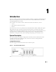
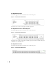
16 1-Gigabit Ethernet Ports The following figure illustrates the PowerConnect 2716 front panel. Figure 1-2. PowerConnect 2716 Front Panel The PowerConnect 2716 switch supports 16 GbE copper ports. 24 1-Gigabit Ethernet Ports + 2 SFP Combo ports The following figure illustrates the PowerConnect 2724 front panel. Figure 1-3. PowerConnect 2724 Front Panel The PowerConnect 2724 switch supports 24 GbE copper ports and has two SFP combo ports (1000BASE-SX or 1000BASE-LX).
Features General Features Head of Line Blocking Prevention Head of Line (HOL) blocking results in traffic delays and frame loss caused by traffic competing for the same egress port resources. HOL blocking queues packets, and the packets at the head of the queue are forwarded before packets at the end of the queue.
Auto Negotiation Auto negotiation allows an Ethernet switch to advertise modes of operation. The auto negotiation function provides the means to exchange information between two Ethernet switches that share a point-to-point link segment, and to automatically configure both Ethernet switches to take maximum advantage of their transmission capabilities. Port advertisement allows the system administrator to configure the port speeds advertised.
MAC Address Supported Features MAC Address Capacity Support The PowerConnect 2708, 2716, and 2724 switches support a total of 8K MAC addresses, and the PowerConnect 2748 supports a total of 16K MAC addresses. Auto-Learning MAC Addresses The switch enables MAC address auto-learning from incoming packets. The MAC addresses are stored in the Bridging Table. Automatic Aging for MAC Addresses MAC addresses from which no traffic is received for a given period of time are aged out.
VLAN Supported Features VLAN Support VLANs are collections of switching ports that comprise a single broadcast domain. Packets are classified as belonging to a VLAN based on either the VLAN tag or based on a combination of the ingress port and package contents. Packets sharing common attributes can be grouped in the same VLAN. Port Based Virtual LANs (VLANs) Port-based VLANs classify incoming packets to VLANs based on their ingress port.
A CoS is defined by the user, whereby packets are related to the same Class of Service. After a packet has been classified, it is assigned to one of the queues. The PowerConnect 2708/2716/2724/2748 system can classify according to IPv4 information (DSCP). Class Of Service 802.1p Support The IEEE 802.1p signaling technique is an OSI Layer 2 standard for marking and prioritizing network traffic at the data link/MAC sub-layer. 802.1p traffic is classified and sent to the destination.
2 Hardware Description Switch Port Configurations PowerConnect 2708/2716/2724/2748 Front Panel Port Description The Dell™ PowerConnect™ 2708, 2716, 2724 and 2748 switches use 10/100/1000BASE-T ports on the front panel for connecting to a network. The Gigabit Ethernet ports can operate at 10, 100 or 1000 Mbps. These ports support autonegotiation, duplex mode (Half or Full duplex), and flow control. The combo 1000 Mbps optical ports can only operate at 1000 Mbps, full-duplex mode.
Figure 2-2. PowerConnect 2708 Back Panel Figure 2-3. PowerConnect 2716 Front Panel On the front panel, there are 16 ports, which are numbered 1 to 16, top down and left to right. On each port there are LEDs to indicate the port status. On the left side of the front panel is the Managed Mode LED which indicates the Ethernet switch operational status. The Power LED on the front panel indicates whether the device is powered on or not.
Figure 2-5. PowerConnect 2724 Front Panel On the front panel there are 24 ports which are numbered 1 to 24, top down and left to right. On each port there are LEDs to indicate the port status. There are two SFP (Small Form-Factor Plugable) ports, designated as ports 23 and 24, for fiber connection.
Figure 2-7. PowerConnect 2748 Front Panel On the front panel, there are 48 ports, which are numbered 1 to 48, top down and left to right. On each port, there are LEDs to indicate the port status. There are four SFP (Small FormFactor Plugable) ports, designated as ports 45, 46, 47 and 48, for fiber connection. The four combo ports are logical ports with two physical connections: • An RJ-45 connection for Twisted Pair (TP) copper cabling.
Physical Dimensions The PowerConnect 2708 switch has the following physical dimensions: • Height — 43.2 mm (1.7008 in.) • Width — 256 mm (10.079 in.) • Depth — 161.7 mm (6.366 in.) The PowerConnect 2716 and PowerConnect 2724 switches have the following physical dimensions: • Height — 43.2 mm (1.7008 in.) • Width — 330 mm (12.992 in.) • Depth — 230.50 mm (9.075 in.) The PowerConnect 2748 switch has the following physical dimensions: • Height — 43.2 mm (1.70 in.) • Width — 440 mm (17.
Table 2-2. Managed Mode LED Indications LED Color Description Green Flashing Indicates diagnostics in progress, firmware loading, or Managed Mode transition. Green Solid Indicates the switch is in Managed Mode. Amber Solid Diagnostics has failed. Amber Flashing No valid image. Off Indicates Unmanaged mode or Secure mode (2748 only). Fan LED (2748 only) On the PowerConnect 2748 front panel there is a fan LED. The following table describes the fan status LED indications. Table 2-3.
Table 2-4. RJ-45 Copper based 10/100/ 1000BASE-T LED Indications LED Color Description Left LED Green Static The port is linked at 1000 Mbps. Green Flashing The port is transmitting or receiving data at 1000 Mbps. Amber Static The port is linked at either 10 or 100 Mbps. Amber Flashing The port is transmitting or receiving data at 10 or 100 Mbps. Off The port is currently not operating Green Static The port is currently transmitting in Full Duplex mode.
Switch Ventilation Fan The PowerConnect 2748 switch has three fans and the PowerConnect 2724 switch has one fan for system ventilation. The PowerConnect 2708 and PowerConnect 2716 devices have no internal fans. Cables, Port Connections, and Pinout Information This section explains the switch physical interfaces, and provides information about cables and port connections. Copper cable diagnostics are supported.
Table 2-7. RJ-45 Pin Number Allocation for 10/100/ 1000BASE-T Ethernet Port Pin No Function 1 TxRx 1+ 2 TxRx 1- 3 TxRx 2+ 4 TxRx 2- 5 TxRx 3+ 6 TxRx 3- 7 TxRx 4+ 8 TxRx 4- SFP Ports The PowerConnect 2724 switch supports two SFP transceivers combo ports, and the PowerConnect 2748 switch supports four SFP transceivers combo ports for various fiber-based modules (1000BASE-SX or 1000BASE-LX). Only one of the two physical connections of a combo port can be used at any time.
Pin Connections for SFP Interfaces Table 2-8. SFP Pin Connections Pin No Use 1 Transmitter ground (common with receiver ground) 2 Transmitter fault 3 Transmitter disable; laser output disabled on high or open. 4 Module definition 2; data line for serial ID. 5 Module definition 1; clock line for serial ID. 6 Module definition 0; grounded within the module. 7 Rate select; no connection required. 8 Loss of signal indication; logic 0 indicates normal operation.
3 Installing the Dell™ PowerConnect™ 27XX This chapter contains information about unpacking, installation procedures, and how to make cable and port connections for the PowerConnect 2708, 2716, 2724, and 2748 devices. Installation Precautions CAUTION: Before performing any of the following procedures, read and follow the safety instructions located in the Product Information Guide.
to Managed Mode. The chapter "Starting and Configuring the Dell™PowerConnect™ 2708/2716/2724/2748 for Managed Mode Operation" explains how to set the switch to Managed Mode. Site Requirements The PowerConnect 2708/2716/2724/2748 devices can be mounted in a standard equipment rack, placed on a tabletop, or mounted on the wall. Before installing the unit, verify that the site selected for the device meets the following site requirements: • Power — The device is installed within 1.
Handling Static Sensitive Devices NOTICE: Static electricity can damage electronic Ethernet switch system. To avoid damage, keep staticsensitive Ethernet switches in their static-protective packages until they are ready to be installed. To reduce the possibility of electrostatic discharge, observe the following precautions: • Limit your movement. Movement can cause static electricity to build up around your person. • Handle the Ethernet switches carefully, holding it by its edges or its frame.
Mounting the Device The following mounting instructions apply to the PowerConnect 2708/2716/2724/2748 devices. There are three device mounting options: • Installing in a Rack • Installing on a Flat Surface • Installing on a Wall Installation Precautions CAUTION Before performing any of the following procedures, read and follow the safety instructions located in your Product Information Guide.
Installing the Device The following mounting instructions apply to all three hardware configurations of PowerConnect 2708, 2716, 2724 and 2748 devices. The section describes how to install a single device as a standalone device. Installing the Device in a Rack CAUTION: Disconnect all cables from the unit before mounting the device in a rack or cabinet. CAUTION: When mounting multiple devices into a rack, mount the devices from the bottom up.
Installing the Device on a Flat Surface The device can be installed on a flat surface, such as a desk-top, if it is not installed on a rack or on a wall. The surface must be able to support the weight of the device and the device cables. 1 Attach the self-adhesive rubber pads (provided with the device) on each marked location on the bottom of the chassis. 2 Set the device on a flat surface, while leaving 5.08 cm (2 inches) on each side, and 12.7 cm (5 inches) at the back.
7 Secure the unit to the wall with screws (not provided). Ensure that the ventilation holes are not obstructed. Figure 3-4. Mounting Device on a Wall Connecting the Device to AC Power Supply 1 Using a 5-foot (1.5 m) standard power cable with safety ground connected, connect the power cable to the AC connector located on the back panel.
Figure 3-5. Back Panel Power Connector 2 After connecting the device to a power source, confirm that the device is connected and operating correctly by examining the LEDs on the front panel. Connecting the Device to the Network To connect to an uplink port, use Category 5 Unshielded Twisted-Pair (UTP) cables with RJ-45 connectors at both ends.
4 Starting and Configuring the Dell™ PowerConnect™ 27XX NOTE: Before proceeding, read the release notes for this product. The release notes can be downloaded from support.dell.com. NOTE: It is recommended that the most recent revision of the user documentation is obtained from the Dell Support Website at support.dell.com.
The following information must be obtained from the network administrator before configuring the device: • The IP address to be assigned to the VLAN 1 interface through which the device is to be managed (by default, every port is a member of the VLAN 1 in Managed Mode). • The IP subnet mask for the network • The default gateway (next hop router) IP address for configuring the default route.
2 Enter the IP address, Subnet Mask and Default Gateway as supplied by the System Administrator. 3 Click Apply Changes. The switch is configured with the updated configuration parameters.
5 Using the Dell OpenManage™ Switch Administrator This section provides an introduction to the Embedded Web Server (EWS), which serves HTML pages through which the user can monitor the switch interface. Understanding the Interface The home page contains a Tree View — located on the left side of the home page. The tree view provides an expandable view of the features and their components. Figure 5-1.
The following table lists the interface components with their corresponding numbers. Table 5-1. Interface Components Component Description 1 The tree view contains a list of the different Ethernet switch features. The functions in the tree view provide a view of all the components under a specific feature. 2 The Ethernet switch view provides information about switch ports, current configuration and status, table information, and feature components.
Using the OpenManage Switch Administrator Buttons This section describes the buttons found on the Dell™ PowerConnect™ OpenManage Switch Administrator interface. Information Buttons Information buttons provide access to on-line support and online help, as well as information about the OpenManage Switch Administrator interfaces. Table 5-2. Information Buttons Button Description Support Opens the Dell Support page at support.dell.com.
Table 5-3. PowerConnect Switch Management Buttons Button Description Apply Changes Applies changes to the Ethernet Switch. Refresh Refreshes Ethernet Switch information. Print Prints the Network Management System page or table information. Starting the Application 1 Open a Web browser. 2 Enter the Ethernet Switch IP address (the default IP address is: 192.168.2.1) in the address bar and press .
Resetting the Device The Reset page resets the device. To open the Reset page, click Reset in the tree view. Figure 5-2. Reset 1 Click Reset. A confirmation message displays. 2 Click OK. The device is reset.
Displaying Configuration on Demand The EWS shortens user wait time by providing Data Display on Demand. When the system retrieves vast amounts of configuration data, the data is divided into groups. The system administrator can peruse the configuration information by either selecting a specific interface or using the Previous and Next links. The following screen displays an example of data display on demand: Figure 5-3.
6 Configuring System Information This section provides information for defining system parameters including switch status features, downloading switch software, and modifying switch parameters. Defining Switch Information Viewing the Switch Status The Switch Status page contains parameters for configuring and viewing general switch information, including the Product Name, Firmware Version, the system MAC Address, Asset Tag, Service Tag, System Name, Location Name, Serial Number, and System Up Time.
Asset Tag (0-16 Characters) — Specifies the user-defined switch reference. Service Tag — The service reference number used when servicing the switch. System Name (0-32 Characters) — Defines the user-defined switch name. Location Name (0-32 Characters) — The location where the system is currently running. Serial Number — Specifies the device’s unique serial number, assigned by the manufacturer. System Up Time— Specifies the amount of time since the last switch reset.
Figure 6-2. IP Addressing DHCP — The DHCP client can be enabled to acquire the network configuration dynamically. The DHCP default value is Disable. This field enables the DHCP client. IP Address — Specifies the static IP Address currently assigned to the device. Subnet Mask— Specifies the subnet mask of the static IP Address, currently assigned to the device. Default Gateway — Specifies the static Default Gateway Address, currently assigned to the device.
Configuring DHCP Client 1 Open the IP Addressing page. 2 Change the DHCP to Enable. 3 Click Apply Changes. The switch requests from the DHCP server to assign a new dynamic IP Address, Subnet Mask, and Default Gateway Address to manage the device. The dynamic DHCP IP Address, DHCP Subnet Mask, and DHCP Default Gateway Address are displayed. NOTE: The displayed values are not configured to the device. Record the updated dynamic fields. 4 Check the box for Apply DHCP Address.
Defining Interface Configuration The Interface Configuration page enables the user to set the port parameters, such as port speed, port type, and additional port operational attributes. To open the page, click Interface Configuration in the tree view. Figure 6-3. Interface Configuration Interface — The current interface type for a port or a LAG, for which interface parameters are defined.
Current Port Speed — The actual synchronized port speed, in bits per second. Admin Duplex — Full Duplex (FDX) indicates that the switch interface supports transmission between the device and another station, in both directions simultaneously. Half Duplex (HDX) indicates that the interface supports transmission between the device and the other station in one direction only at a time. Current Duplex Mode — The synchronized port duplex mode of transmission.
Auto — Use to automatically detect the cable type. Current MDI/MDIX — Displays the current MDI/MDIX status of the port. LAG — Specifies if port is a part of a LAG (Link Aggregated Group). Configuring the Interface 1 Open the Interface Configuration page. 2 Define the fields. 3 Click Apply Changes. The switch port parameters are applied and displayed in the currently updated window. Viewing Jumbo Frames Jumbo Frames transports identical amounts of data in fewer frames.
Current — Shows what the current status is for Jumbo Frames support. After Reset — Indicates the Jumbo Frames status after the next time the switch is powered on. Enabling Jumbo Frames 1 Open the Jumbo Frames page. 2 Select Enabled in the Jumbo Frames field. 3 Click Apply Changes. The Jumbo Frames are enabled on the device after power cycling. Creating VLAN Membership The VLAN Membership page contains a port table for assigning ports to VLANs.
Blank — The interface is not a VLAN member. Packets associated with the interface are not forwarded. Show VLAN ID — Displays the list of the VLAN IDs as defined in the switch. Create VLAN — Designates the ID of the particular VLAN defined. VLAN Name — Defines a new VLAN in the switch. Remove VLAN — Removes a selected VLAN from the switch. Showing/Creating VLANs 1 Open the VLAN Membership page. 2 Select VLAN ID or Create VLAN field. 3 Click Apply Changes. The switch VLAN change is applied.
Figure 6-6. VLAN Interface Settings Interface — Indicates the interface number of the port, LAG, or VLAN that is configured on the switch. PVID (1-4095) — Assigns a VLAN ID to untagged packets. The possible field values are 1-4094. VLAN 1 is used as the default VLAN. The default VLAN is only used as a port default VLAN ID (PVID). VLAN 1 cannot be deleted from the system. VLAN 4095 is defined as the discard VLAN, thus the packets classified to this VLAN are dropped.
The LAG Aggregation Configuration page displays the LAGs defined, and the ports aggregated and assigned to them. To open the page, click LAG Membership in the tree view. Figure 6-7. LAG Aggregation Configurfation Ports — Specifies the port(s) aggregated into the LAG and assigned to which LAG. LAG Group — Adds a port to a LAG and indicates the specific LAG to which the port belongs. Adding a Port to a LAG 1 Open the LAG Aggregation Configuration page.
Managing System Files Use the File Management section to manage switch software, the image file, and the configuration files. Files can be downloaded or uploaded via a TFTP server. This applies to the PowerConnect 2748 switch configuration only. The configuration file structure consists of the following configuration files: 54 • Startup Configuration File — Contains the commands required to reconfigure the device to the same settings as when the device is powered down or rebooted.
Downloading Files From Server The File Download page contains fields for downloading files from the TFTP server. To open the page, click File Download in the tree view. Figure 6-8. File Download (PowerConnect 2708, 2716, and 2724 Switch Configuration) TFTP Server IP Address — The TFTP Server IP Address from which files are downloaded. Source File Name (1-64 Characters) — Specifies which file is downloaded. Destination File — The destination file type to which the file is downloaded.
Figure 6-9. File Download (PowerConnect 2748 Switch Configuration) Firmware Download — The Firmware file is downloaded. If Firmware Download is selected, the Configuration Download fields are grayed out. Configuration Download — The Configuration file is downloaded. If Configuration Download is selected, the Firmware Download fields are grayed out. Download via TFTP — Enables initiating an image download via the TFTP server. Download via HTTP — Enables initiating an image download via the HTTP protocol.
Configuration Download Server IP Address (1-159 Characters) — The Server IP Address from which the configuration files are downloaded. Source File Name — Indicates the configuration files to be downloaded. Downloading Files from Server 1 Open the File Download page. 2 Define the file type to download. 3 Define the fields on the page. 4 Click Apply Changes. The software file is downloaded to the switch.
Destination File Name (1-159 Characters) — Indicates the Configuration file path to which the file is uploaded. NOTE: This list of user-defined configuration files only appears if the user created backup configuration files. For example, if the user copied the running configuration file to a user-defined configuration file called BACKUP-SITE-1, this list appears on the File Upload to Server page and the BACKUP-SITE-1 configuration file appears in the list.
Use Saved IP — Uses the saved IP address for device configuration, when selected. Use Current IP — Uses the current IP address for device configuration, when selected. Default User — Uses the default user for device configuration, when selected. Default Password — Uses the default password for device configuration, when selected. Save User/Password — Saves the currently configured device user and password, when selected.
Local User Database The Local User Database page contains fields for defining User Names, Passwords and access Level. To open the page, click the Local User Database in the tree view. Figure 6-12. Local User Database User Name (1-20 Characters) — Defines a User-defined user name. The Local User Database User Name can be from 1-20 characters long. New — A new User Name to be added to the list. Level — Indicates the User Access Level. Two Access Levels can be defined: Read/Write, and Read Only.
Adding a User to the Local User Database 1 Open the Local User Database page. 2 Select New and enter the field. 3 Complete the fields for the new user. 4 Click Apply Changes. The new user information is saved and the switch is updated. Deleting a User from the Local User Database 1 Open the Local User Database page. 2 Select User Name in the selection list. 3 Check the Remove box. 4 Click Apply Changes. The User Name is removed from the list and the switch is updated.
Figure 6-13. Integrated Cable Test Port — The port to which the cable is connected. Test Result — Specifies the cable test results. One of the following results may apply: No Cable — There is no cable connected to the port. Open Cable — The cable is not connected on the other side. Short Cable — A short has occurred in the cable. OK — The cable test passed successfully. Cable Fault Distance — Indicates the distance from the port where the cable error occurred.
Optical Transceivers Diagnostics The Optical Transceivers Diagnostics page contains fields for performing tests on Fiber Optic cables. The optical transceiver provides access to a set of parameters that can be monitored and displayed to the system administrator. NOTE: The Optical Transceivers Diagnostics analysis applies only to PowerConnect 2724 device’s SFP ports, which support the digital diagnostic standard SFF-4872. To open the page, click Optical Transceivers Diagnostics in the tree view. Figure 6-14.
3 Click show All. The test is performed and the Optical Transceiver Diagnostics test table opens. Port Mirroring The Port Mirroring mechanism monitors and mirrors the network traffic by forwarding copies of incoming and outgoing packets from monitored ports (up to four ports) to a monitoring port. Port Mirroring can be configured by selecting a specific port to copy all packets, and different ports from which the packets are copied.
Enabling Storm Control When Layer 2 frames are forwarded, Broadcast, Multicast and Unknown Unicast frames are flooded to all ports on the designated VLANs on the switch. When the switch experiences an excessive amount of Broadcast/Multicast/Unknown Unicast frames on network links, Storm Control mechanism controls the amount of frames entering the switch. The Storm Control page is used to configure the settings of packet Storm Control. Storm Control can be enabled or disabled per port.
Broadcast Rate Threshold (70-285000) — The rate of Broadcast threshold ranges from 70-285,000 packets per second. The default value is zero. Modifying PowerConnect 2708 Storm Control Port Parameters 1 Open the Storm Control page. 2 Enter the fields. 3 Click Apply Changes. The Storm Control port parameters are saved to the PowerConnect 2708 switch.
Port — The port from which the storm control is enabled. Broadcast Control — Enables or disables forwarding Broadcast packets on the switch. The default is Disable. Modifying PowerConnect 2716/2724 Storm Control Port Parameters 1 Open the Storm Control page. 2 Enter the fields. 3 Click Apply Changes. The Storm Control port parameters are saved to the PowerConnect 2716/2724 switch.
The range is 3500 - 1000000. The default value is 3500. Modifying PowerConnect 2748 Storm Control Port Parameters 1 Open the Storm Control page. 2 Enter the fields. 3 Click Apply Changes. The Storm Control port parameters are saved to the PowerConnect 2748 switch.
7 Configuring Quality of Service This section provides information for defining and configuring Quality of Service (QoS) parameters. Quality of Service (QoS) Overview An implementation example that requires QoS includes certain types of traffic such as Voice, Video, and real-time traffic, which can be assigned a high priority queue, while other traffic can be assigned a lower priority queue. The result is an improved traffic flow for traffic with high demand. The system supports four queues per port.
Packets arriving untagged are assigned a default VPT value, which is set on a per port basis. The assigned VPT is used to map the packet to the egress queue. DSCP values can be mapped to priority queues. DSCP mapping is enabled on a per-system basis. The following table contains the default DSCP mapping to egress queue values: Table 7-2.
Defining CoS Settings Class of Service global parameters are set from the CoS Settings page. Configuring QoS Settings The CoS Settings page contains fields for enabling or disabling CoS. In addition, the Trust mode can be selected. The Trust Mode relies on predefined fields within the packet to determine the egress queue. To open the page, click CoS Settings in the tree view. Figure 7-1. CoS Settings Trust Mode — Defines which fields within the packet are used to determine the egress queue.
NOTE: The interface Trust settings overrides the global Trust setting. Strict Priority — Specifies if traffic scheduling is based strictly on the queue priority. This is the default value for queues. WRR — Specifies if traffic scheduling is based on the Weighted Round Robin (WRR) weights to assigned egress queues. Configuring the Trust Mode: 1 Open the CoS Settings page. 2 Define the Trust Mode field. 3 Click Apply Changes. Trust Mode is enabled on the Ethernet switch.
Mapping a CoS value to a Queue 1 Open the Cos to Queue page. 2 Define the egress queue for each CoS value. 3 Click Apply Changes. The CoS value is mapped to an egress queue, and the switch is updated. Mapping DSCP Values to Queues The DSCP to Queue page provides fields for defining egress queue to specific DSCP fields. To open the page, click DSCP to Queue in the tree view. Figure 7-3. DSCP to Queue DSCP In — The values of the DSCP field within the incoming packet.
8 Viewing Statistics RMON Statistics Remote Monitoring (RMON) is an extension to the Simple Network Management Protocol (SNMP) which provides network traffic statistics. RMON defines current and historical MAC-layer statistics and control objects, allowing real-time information to be captured across the entire network. The system provides a means to collect the statistics defined in RMON and to view the results using the Web management interface. There is no SNMP management interface in the system.
Received Bytes (Octets) — Number of octets received on the interface since the system was last reset. This number includes bad packets and FCS octets, but excludes framing bits. Received Packets — Number of packets received on the interface, including bad packets, Multicast and Broadcast packets, since the system was last reset. Broadcast Packets Received — Number of good Broadcast packets received on the interface since the system was last reset. This number does not include Multicast packets.
Glossary This glossary contains key technical words of interest. A Auto-negotiation Allows 10/100 Mpbs or 10/100/1000 Mbps Ethernet ports to establish for the following features: • Duplex/ Half Duplex Mode • Flow Control • Speed B Back Pressure A mechanism used with Half Duplex mode that enables a port not to receive a message. Bandwidth Bandwidth specifies the amount of data that can be transmitted in a fixed amount of time.
Broadcast Storm An excessive amount of broadcast messages simultaneously transmitted across a network by a single port. Forwarded message responses are heaped onto the network, overloading network resources or causing the network to time out. C Class of Service Class of Service (CoS). Class of Service is the 802.1p priority scheme. CoS provides a method for tagging packets with priority information.
F Flow Control Enables lower speed Ethernet switch modules to communicate with higher speed Ethernet switch module s, that is, that the higher speed Ethernet switch module refrains from sending packets. Fragment Ethernet packets smaller than 576 bits. Frame Packets containing the header and trailer information required by the physical medium. G Gigabit Ethernet Gigabit Ethernet transmits at 1000 Mbps, and is compatible with existing 10/100 Mbps Ethernet standards. H HOL Head of Line. Packets are queued.
Ingress Port Ports on which network traffic is received. IP Internet Protocol. Specifies the format of packets and there addressing method. IP addresses packets and forwards the packets to the correct port. IP Address Internet Protocol Address. A unique address assigned to a network Ethernet switch module with two or more interconnected LANs or WANs. J Jumbo Frames Enables transporting the identical data in fewer frames. Jumbo Frames reduce overhead, lower processing time, and ensures fewer interrupts.
MAC Layer A sub-layer of the Data Link Control (DTL) layer. Managed Mode Provides switch management through a web interface, and maintains the device configuration through power cycles. Mask A filter that includes or excludes certain values, for example parts of an IP address. MDI Media Dependent Interface. A cable used for end stations. MDIX Media Dependent Interface with Crossover (MDIX). A cable used for hubs and switches. Multicast Transmits copies of a single packet to multiple ports.
A set of rules that governs how Ethernet switch modules exchange information across networks.
Q QoS Quality of Service. QoS allows network managers to decide how and what network traffic is forwarded according to priorities, application types, and source and destination addresses. R RMON Remote Monitoring. Provides network information to be collected from a single workstation. Router A Ethernet switch module that connects to separate networks. Routers forward packets between two or more networks. Routers operate at a Layer 3 level.
TFTP Trivial File Transfer Protocol. Uses User Data Protocol (UDP) without security features to transfer files. Trunking Link Aggregation. Optimizes port usage by linking a group of ports together to form a single trunk (aggregated groups). U Unicast A form of routing that transmits one packet to one user. V VLAN Virtual Local Area Networks. Logical subgroups with a Local Area Network (LAN) created via software rather than defining a hardware solution. W WAN Wide Area Networks.