
Setup Guide


Dell PowerConnect J-Series J-SRX100 Services Gateway
Quick Start
Use the instructions in this quick start to help you connect the Dell PowerConnect
J-Series J-SRX100 Services Gateway to your network. For details, see the J-SRX100
Services Gateway Hardware Guide at http://www.support.dell.com/manuals.
(Regulatory model number SRX100)
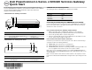
J-SRX100 Services Gateway Front Panel
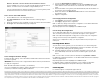
J-SRX100 Services Gateway Back Panel
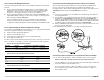
J-SRX100 Services Gateway Models
The following models of J-SRX100 Services Gateway are available:
Connecting and Configuring the J-SRX100 Services Gateway
Use the instructions below to connect and set up the J-SRX100 Services Gateway to
protect your network. Refer to the LEDs on the front panel of the device to help you
determine the status of the device.
Part 1: Connect the Services Gateway to Earth Ground
1. Obtain a grounding cable—14 AWG single-strand, 4 A—with a ring-type,
vinyl-insulated TV14-6R lug or equivalent attached by a licensed electrician.
2. Connect the grounding cable to a proper earth ground.
3. Place the grounding cable lug over the grounding point on the middle rear of the
chassis, and secure the lug with one M3 screw.
Part 2: Connect the Power Cable to the Device
Connect the power cable to the device and a power source. We recommend using a
surge protector. Note the following indications:
POWER LED (green): The device is receiving power.
STATUS LED (green): The device is operating normally.
ALARM LED (amber): The device is operating normally, and may glow amber as a
rescue configuration has not been set. This is not a panic condition.
NOTE:
After a rescue configuration has been set, an amber ALARM LED indicates a
minor alarm, and a solid red ALARM LED indicates that a major problem exists on the
services gateway.
NOTE:
You must allow the device between 5 and 7 minutes to boot up after you have
powered it on. Wait until the STATUS LED is solid green before proceeding to the next
part.
Callout Description Callout Description
1 Power button 4 USB port
2 LEDs (ALARM, POWER, STATUS, HA) 5 Console port
3 Reset Config button 6 Fast Ethernet ports
Callout Description Callout Description
1 Lock for security cable 3 Cable tie holder
2 Grounding point 4 Power supply input
J-SRX100
Device DDR Memory
J-SRX100B 512 MB
J-SRX100H 1 GB
J-SRX100S 1 GB
J-SRX100SU 1 GB