
Troubleshooting
Efficient Video Distribution Networks with.Multicast: IGMP Querier and PIM-DM
6
Without IGMP snooping, multicast packets are broadcast throughout the network, causing unnecessary
traffic. This impedes the efficiency of both the network and every system on the network that has to
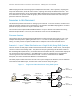
process and drop multicast packets they were not expecting. For example, all three laptops in Figure 2
would receive the traffic although only one or two of them may desire to.
Follow the steps below to set up and test the Multicast topology shown in Figure 2.
Multicast Using IGMP Querier Setup (CLI commands are given below)
Note: Best practice, particularly in a production environment, is to configure new switches before
connecting them into the existing network. In an isolated test network such as this, it is okay to
connect the switches together in the first step, provided they have no significant configuration other
than for management. This will allow the administrator to telnet to each switch for configuring.
Otherwise, use a console cable to each switch for configuring, and make cabling the switches together
the last step.
1. Bring up all three switches and connect them together in a daisy chain with a LAG or single
cable between switches as shown in Figure 2.
2. On all three switches, create VLAN 10. Assign VLAN 10 an IP address on each switch so that
each switch’s VLAN 10 is on the same subnet.
Note: Non-querier switches such as the second and third switch here, do not require a VLAN IP
address, but it is nice to have for management and troubleshooting purposes.
3. For each trunk port (going from one switch to another switch), configure the port in trunk
mode and assign it to VLAN 10.
4. Plug in the server at one end of the network and the clients at the opposite end as shown in
Figure 2.
5. On the two end switches, for each access port (going to a video server or client), configure the
port in access mode and assign them VLAN 10.
6. Provide the server and each client an IP address within the same subnet as VLAN 10. For this
example we gave the video server an IP address of 10.0.0.50, and we gave the clients IP
addresses 10.0.0.51 through 10.0.0.53.
7. From a client, ping the server and all three VLAN IP addresses on the three switches to ensure
the network is configured correctly.
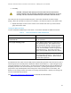
8. Enable IGMP snooping on VLAN 10 on all three switches.
Note: With PowerConnect 5.1 and later firmware, IGMP snooping is enabled globally and on all
VLANs by default. The vlan parameter is used to enable IGMP snooping on a specific VLAN, and
the no parameter is used to remove IGMP snooping from a particular VLAN.
9. Remove IGMP snooping on VLAN 1.
10. Enable IGMP querier on the switch closest to the video server.
On a layer 2 network with a single VLAN, IGMP snooping must be enabled on all switches in the
multicast route. With PowerConnect 5.1, IGMP snooping is enabled by default. A PIM router is not
required for Multicast Routing to occur on a layer 2 network with one VLAN.