Dell™ PowerEdge™ 1600SC Systems User's Guide System Overview Using the Dell OpenManage Server Assistant CD Using the System Setup Program Technical Specifications Using Console Redirection Glossary NOTE: A NOTE indicates important information that helps you make better use of your system. NOTICE: A NOTICE indicates either potential damage to hardware or loss of data and tells you how to avoid the problem. CAUTION: A CAUTION indicates a potential for property damage, personal injury, or death.
Back to Contents Page Technical Specifications Dell™ PowerEdge™ 1600SC Systems User's Guide Microprocessor Expansion Bus Memory Drives Externally Accessible Ports and Connectors Video Power Physical Environmental Specifications Specifications Microprocessor Microprocessor type up to two Intel® Xeon™ microprocessors with a speed of at least 1.
DC power supply (per power supply): Wattage 450 W Voltage 100–240 VAC, 50–60 Hz Heat dissipation 2275 BTU/hr maximum Output hold up time 20 ms minimum Maximum inrush current System battery Under typical line conditions and over the entire system ambient operating range, the inrush current may reach 55 A at 10 ms or less or 25 A at 150 ms or less. CR2032 3.0-V lithium coin cell Physical Height 44.7 cm (17.6 inches) Width 21.8 cm (8.6 inches) Depth 57.41 cm (22.6 inches) Weight 30.
Back to Contents Page Using Console Redirection Dell™ PowerEdge™ 1600SC Systems User's Guide Hardware Requirements Software Requirements Configuring the Host System Configuring the Client System Managing the Host System Remotely Configuring Special Key Functions Console redirection allows you to manage a host (local) system from a client (remote) system by redirecting keyboard input and text output through a serial port. You cannot redirect graphic output.
After configuring the host system, configure the ports and terminal settings for the client (remote) system. NOTE: The examples in this section assume that you have upgraded to Hilgraeve's HyperTerminal Private Edition 6.1 or later. If you are using other terminal emulation software, see the documentation for that software. Configuring the Serial Port 1. Click the Start button, point to Programs→ Accessories→ Communications, and then click HyperTerminal. 2.
l Enter the SCSI setup menus l Update firmware and BIOS (flash the system) l Run utilities on the utility partition NOTE: To run utilities on the host system's utility partition, you must have created the utility partition using Dell OpenManage™ Server Assistant version 6.3.1 or later. Configuring Special Key Functions Console redirection uses ANSI or VT 100/220 terminal emulation, which is limited to basic ASCII characters.
<[> VT 100 <[><0> VT 220 After creating macros for the keys listed in Table B-1, press on the client system's keyboard during terminal emulation to send the escape sequence to the host system. The host system then interprets the sequence as . Additional escape sequences may be required by certain utilities or functions on the host system. Create macros for the additional sequences listed in Table B2.
Back to Contents Page Dell™ PowerEdge™ 1600SC Systems User's Guide Back to Contents Page
Back to Contents Page Dell™ PowerEdge™ 1600SC Systems User's Guide Back to Contents Page
Back to Contents Page System Overview Dell™ PowerEdge™ 1600SC Systems User's Guide Front Bezel Features and Indicators Front-Panel Features Back-Panel Features System Features Supported Operating Systems Power Protection Devices Other Documents You May Need Obtaining Technical Assistance Your system provides a reliable platform for both large and small environments, including small-business and remote-site environments.
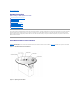
Front-Panel Features Figure 1-3 shows the front-panel features for a system with non-hot-plug SCSI or IDE hard drives. Figure 1-4 shows the front-panel features for a system with hot-plug SCSI hard drives. Figure 1-3. System With Non-Hot-Plug Hard Drives Figure 1-4.
Figure 1-5 shows the back-panel features of the system. NOTE: Figure 1-5 shows a system with optional redundant AC power supplies installed. Figure 1-5. Back-Panel Features Connecting External Devices When connecting external devices to your system, follow these guidelines: l Most devices must be connected to a specific connector and device drivers must be installed before the device will operate properly.
l Optional single-channel RAID controller for SCSI RAID or optional quad-channel RAID controller for IDE RAID l Two 5.25-inch peripheral drive bays that supports the following optional drives: CD, DVD, combination CD/DVD, or tape backup unit (SCSI or IDE) The system board includes the following built-in features: l l l l Six PCI expansion slots: two 32-bit, 33-MHz PCI slots; two 64-bit, 66-MHz PCI slots; two 64-bit, 100-MHz PCI-X slots.
Other Documents You May Need The System Information Guide provides important safety and regulatory information. Warranty information may be included within this document or as a separate document. l The Setting Up Your System document provides an overview of initially setting up your system. l The Installation and Troubleshooting Guide describes how to troubleshoot the system and install or replace system components.
Back to Contents Page Using the Dell OpenManage Server Assistant CD Dell™ PowerEdge™ 1600SC Systems User's Guide Option Description Starting the Server Assistant CD Using the Server Setup Program Updating Drivers and Utilities Using the Utility Partition The Dell OpenManage Server Assistant CD contains utilities, diagnostics, and drivers to help you configure your system. You begin operating system installation with this CD if your operating system is not preinstalled on your system.
Updating Drivers and Utilities You can update drivers and utilities on any system that has Microsoft® Internet Explorer 4.0 or later or Netscape Navigator 6.0 or later installed. When you insert the CD in a system that uses a Microsoft Windows®-based operating system, the system automatically starts the browser and displays the Dell OpenManage Server Assistant main screen. To update drivers and utilities, perform the following steps: 1.
Back to Contents Page Using the System Setup Program Dell™ PowerEdge™ 1600SC Systems User's Guide Entering the System Setup Program System Setup Options Using the System Password Feature Using the Setup Password Feature Disabling a Forgotten Password Asset Tag Utility The System Setup program allows you to view or configure system and hardware device settings.
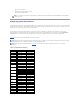
If you are given an option of pressing either to continue or to run the System Setup program, press the key. Using the System Setup Program Table 3-1 lists the keys used to view or change information on the System Setup screens and to exit the program. Table 3-1. System Setup Navigation Keys Keys Action Moves to the next field. Down arrow or Moves to the previous field. Up arrow or Cycles through the settings in a field.
The following options and information fields appear on the main System Setup screen: l System Time — Resets the time on the system's internal clock. l System Date — Resets the date on the system's internal calendar. l Diskette Drive A: — Identifies the type of diskette drive installed in the system. l System Memory — Displays the amount of system memory; this option has no user-selectable settings. l Video Memory — Displays the amount of video memory; this option has no user-selectable settings.
l Integrated Devices — Displays a screen that allows you to configure devices on the system board. See "Integrated Devices Screen." l PCI IRQ Assignment — Displays a screen that allows you to change the IRQ allocated to each of the integrated devices on the PCI bus or any installed expansion card requiring an IRQ. l System Security — Displays a screen that allows you to configure the system password and setup password features, chassis intrusion, and the power button.
Locked. In this state, the system password cannot be changed through the System Password option and cannot be disabled at system start-up by pressing . To unlock the system password, you must enter the setup password in the Setup Password option and then change the Password Status option to Unlocked (default). In this state, the system password can be disabled at system start-up by pressing and then changed through the System Password option.
2. Highlight the System Password option and then press the left- or right-arrow key. 3. Type your new system password. You can use up to seven characters in your password. As you press each character key (or the spacebar key for a blank space), a placeholder appears in the field. The password assignment operation recognizes keys by their location on the keyboard without distinguishing between lowercase and uppercase characters.
** Incorrect password. ** Number of unsuccessful password attempts: 3 System halted! Must power down. The number of unsuccessful attempts made to enter the correct system password can alert you to an unauthorized person attempting to use your system. Even after your system is turned off and on, the previous message is displayed each time an incorrect or incomplete system password is entered.
Operating With a Setup Password Enabled If Setup Password is set to Enabled, you must enter the correct setup password before you can modify the majority of the System Setup options. When you start the System Setup program, the program prompts you to type the password. If you do not enter the correct password in three tries, the system lets you view, but not modify, the System Setup screens—with the following exceptions: l l You can still modify the Date, Time, Keyboard Num Lock, and Speaker options.
An asset tag number can have up to 10 characters. Any combination of characters is valid. For example, at the a:\> prompt, type the following command and press : asset 12345abcde l 3. To delete an asset tag number without assigning a new one, type asset /d and press . When prompted to verify the change to the asset tag number, type y and press . To view the Asset Tag utility help screen, type asset /? and press .
Back to Contents Page Glossary Dell™ PowerEdge™ 1600SC Systems User's Guide The following list defines or identifies technical terms, abbreviations, and acronyms used in your system documents. A Abbreviation for ampere(s). AC Abbreviation for alternating current. adapter card An expansion card that plugs into an expansion-card connector on the computer's system board.
boot routine When you start your system, it clears all memory, initializes devices, and loads the operating system. Unless the operating system fails to respond, you can reboot (also called warm boot) your system by pressing ; otherwise, you must perform a cold boot by pressing the reset button or by turning the system off and then back on. bps Abbreviation for bits per second. BTU Abbreviation for British thermal unit. bus An information pathway between the components of a system.
A chip that controls the transfer of data between the microprocessor and memory or between the micro-processor and a peripheral device such as a disk drive or the keyboard. control panel The part of the system that contains indicators and controls, such as the power switch, hard drive access indicator, and power indicator. conventional memory The first 640 KB of RAM. Conventional memory is found in all systems.
DIP Acronym for dual in-line package. A circuit board, such as a system board or expansion card, may contain DIP switches for configuring the circuit board. DIP switches are always toggle switches, with an ON position and an OFF position. directory Directories help keep related files organized on a disk in a hierarchical, "inverted tree" structure. Each disk has a "root" directory; for example, a c:\> prompt normally indicates that you are at the root directory of hard drive C.
Abbreviation for enhanced integrated drive electronics. EIDE devices add one or more of the following enhancements to the traditional IDE standard: l Data transfer rates of up to 16 MBps l Support for drives other than just hard drives, such as CD and tape drives l Support for hard drives with capacities greater than 528 MB l Support for up to two controllers, each with up to two devices attached EMC Abbreviation for Electromagnetic Compatibility. EMI Abbreviation for electromagnetic interference.
Abbreviation for Fahrenheit. FAT Acronym for file allocation table. The file system structure used by MS-DOS to organize and keep track of file storage. Some other operating systems can optionally use a FAT file system structure. FCC Abbreviation for Federal Communications Commission. flash memory A type of EEPROM chip that can be reprogrammed from a utility on diskette while still installed in a system; most EEPROM chips can only be rewritten with special programming equipment.
h Abbreviation for hexadecimal. A base-16 numbering system, often used in programming to identify addresses in the system's RAM and I/O memory addresses for devices. The sequence of decimal numbers from 0 through 16, for example, is expressed in hexadecimal notation as 0, 1, 2, 3, 4, 5, 6, 7, 8, 9, A, B, C, D, E, F, 10. In text, hexadecimal numbers are often followed by h. heat sink A metal plate with metal pegs or ribs that help dissipate heat. Most microprocessors include a heat sink.
Each peripheral connection must be assigned an IRQ number. For example, the first serial port in your system (COM1) is assigned to IRQ4 by default. Two devices can share the same IRQ assignment, but you cannot operate both devices simultaneously. ITE Abbreviation for information technology equipment. jumper Jumpers are small blocks on a circuit board with two or more pins emerging from them. Plastic plugs containing a wire fit down over the pins. The wire connects the pins and creates a circuit.
local bus On a system with local-bus expansion capability, certain peripheral devices (such as the video adapter circuitry) can be designed to run much faster than they would with a traditional expansion bus. Some local-bus designs allow peripherals to run at the same speed and with the same width data path as the system's microprocessor. LPTn The device names for the first through third parallel printer ports on your system are LPT1, LPT2, and LPT3. m Abbreviation for meter(s).
memory manager A utility that controls the implementation of memory in addition to conventional memory, such as extended or expanded memory. memory module A small circuit board containing DRAM chips that connects to the system board. MHz Abbreviation for megahertz. microprocessor The primary computational chip inside the system that controls the interpretation and execution of arithmetic and logic functions. Software written for one microprocessor must usually be revised to run on another microprocessor.
multifrequency monitor A monitor that supports several video standards. A multifrequency monitor can adjust to the frequency range of the signal from a variety of video adapters. mV Abbreviation for millivolt(s). NDIS Abbreviation for Network Driver Interface Specification. NIC Acronym for network interface controller. NLM Abbreviation for NetWare® Loadable Module. NMI Abbreviation for nonmaskable interrupt.
partition A feature of the operating system that allows you to divide a hard drive into multiple physical sections called partitions. Each partition can contain multiple logical drives. PCI Abbreviation for Peripheral Component Interconnect. A standard for local-bus implementation. peripheral device An internal or external device—such as a printer, a disk drive, or a keyboard—connected to a system.
Acronym for redundant array of independent disks. RAM Acronym for random-access memory. The system's primary temporary storage area for program instructions and data. Each location in RAM is identified by a number called a memory address. Any information stored in RAM is lost when you turn off your system. read-only file A read-only file is one that you are prohibited from editing or deleting. A file can have read-only status if: l Its read-only attribute is enabled.
Abbreviation for SCSI device management system. SDRAM Acronym for synchronous dynamic random-access memory. sec Abbreviation for second(s). SEC Abbreviation for single-edge contact. serial port An I/O port used most often to connect a modem to your system. You can usually identify a serial port on your system by its 9-pin connector. service tag number A bar code label on the system that identifies it when you call for technical support.
syntax The rules that dictate how you must type a command or instruction so that the system understands it. system board As the main circuit board, the system board usually contains most of your system's integral components, such as the following: l Microprocessor l RAM l Controllers for standard peripheral devices, such as the keyboard l Various ROM chips Frequently used synonyms for system board are motherboard and logic board.
tpi Abbreviation for tracks per inch. UL Abbreviation for Underwriters Laboratories. UMB Abbreviation for upper memory blocks. upper memory area The 384 KB of RAM located between 640 KB and 1 MB. If the system has an Intel386 or higher microprocessor, a utility called a memory manager can create UMBs in the upper memory area, in which you can load device drivers and memory-resident programs. UPS Abbreviation for uninterruptible power supply.
previous standards. To display a program at a specific resolution, you must install the appropriate video drivers and your monitor must support the resolution. Similarly, the number of colors that a program can display depends on the capabilities of the monitor, the video driver, and the amount of video memory installed for the video adapter.
Abbreviation for watt(s). WH Abbreviation for watt-hour(s). write-protected Read-only files are said to be write-protected. You can write-protect a 3.5-inch diskette by sliding its write-protect tab to the open position or by setting the write-protect feature in the System Setup program. XMM Abbreviation for extended memory manager, a utility that allows application programs and operating systems to use extended memory in accordance with the XMS. XMS Abbreviation for eXtended Memory Specification.