Dell™ PowerEdge™ 1750 Systems Installation and Troubleshooting Guide Introduction Indicators, Messages, and Codes Finding Software Solutions Running the System Diagnostics Troubleshooting Your System Installing System Options Installing Drives Getting Help Jumpers and Connectors I/O Connectors Abbreviations and Acronyms NOTE: A NOTE indicates important information that helps you make better use of your computer.
Back to Contents Page Jumpers and Connectors Dell™ PowerEdge™ 1750 Systems Installation and Troubleshooting Guide Jumpers—A General Explanation System Board Jumpers System Board Connectors SCSI Backplane Board Connectors Disabling a Forgotten Password This section provides specific information about the jumpers on the system board. It also provides some basic information on jumpers and switches and describes the connectors and sockets on the various boards in the system.
Table A-1. System Board Jumper Settings Jumper Setting Description PASSWD (default) The password feature is enabled. The password feature is disabled. NVRAM_CLR (default) The configuration settings are retained at system boot. The configuration settings are cleared at next system boot. (If the configuration settings become corrupted to the point where the system will not boot, install the jumper plug and boot the system. Remove the jumper before restoring the configuration information.
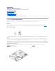
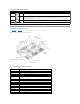
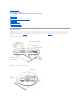
PS_SIG Power supply signal connector RAID Socket for optional ROMB card RAID BAT Backup battery connector for ROMB card SCSI_B External SCSI connector SERIAL Serial port connector USBn USB connector VGA VGA connector SCSI Backplane Board Connectors Figure A-4 shows the location of the connectors on the top of the SCSI backplane board. Figure A-4.
Back to Contents Page
Back to Contents Page I/O Connectors Dell™ PowerEdge™ 1750 Systems Installation and Troubleshooting Guide I/O Connectors Serial Connector PS/2-Compatible Keyboard and Mouse Connectors Video Connector USB Connector RAC Ethernet Connector Integrated NIC Connector Network Cable Requirements I/O Connectors I/O connectors are the gateways that the system uses to communicate with external devices, such as a keyboard, mouse, printer, or monitor. This section describes the various connectors on your system.
Table B-1 shows the icons used to label the connectors on the system. Table B-1. I/O Connector Icon Icon Connector Serial connector Mouse connector Keyboard connector Video connector USB connector NIC connector RAC Ethernet connector Serial Connector Serial connectors support devices such as external modems, printers, and mice that require serial data transmission. The serial connector uses a 9-pin Dsubminiature connector.
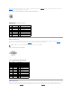
The PS/2-compatible keyboard and mouse cables attach to 6-pin, miniature DIN connectors. Figure B-4 illustrates the pin numbers for these connectors and Table B-3 defines the pin assignments for these connectors. Figure B-4. PS/2-Compatible Keyboard and Mouse Connector Pin Numbers Table B-3.
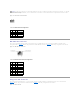
NOTICE: Do not attach a USB device or a combination of USB devices that draw a maximum current of more than 500 mA per channel or +5 V. Attaching devices that exceed this threshold may cause the USB connectors to shut down. See the documentation that accompanied the USB devices for their maximum current ratings. Figure B-6. USB Connector Pin Numbers Table B-5.
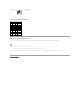
Table B-7. NIC Connector Pin Assignments Pin Signal I/O Definition 1 TP0+ I/O Data0 (+) 2 TP0– I/O Data0 (–) 3 TP1+ I/O Data1 (+) 4 TP2+ I/O Data2 (+) 5 TP2– I/O Data2 (–) 6 TP1– I/O Data1 (–) 7 TP3+ I/O Data3 (+) 8 TP3– I/O Data3 (–) Network Cable Requirements The NIC supports a UTP Ethernet cable equipped with a standard RJ45-compatible plug. Observe the following cabling restrictions. NOTICE: To avoid line interference, voice and data lines must be in separate sheaths.
Back to Contents Page Abbreviations and Acronyms Dell™ PowerEdge™ 1750 Systems Installation and Troubleshooting Guide The following list defines or identifies technical terms, abbreviations, and acronyms used in your user documents.
CPU central processing unit DAC digital-to-analog converter DAT digital audio tape dB decibel(s) dBA adjusted decibel(s) DC direct current DDR dual data rate DIMM dual in-line memory module DIN Deutsche Industrie Norm DIP dual in-line package DMA direct memory access DOC Department of Communications (in Canada) dpi dots per inch DRAC Dell remote access card DRAM dynamic random-access memory DS/DD double-sided double-density DS/HD double-sided high-density DSA Dell SCSI Array ECC error chec
EGA enhanced graphics adapter EIDE enhanced integrated drive electronics EMI electromagnetic interference EMM expanded memory manager EMS Expanded Memory Specification EPP Enhanced Parallel Port EPROM erasable programmable read-only memory ESD electrostatic discharge ESDI enhanced small-device interface ESM embedded server management F Fahrenheit FAT file allocation table FCC Federal Communications Commission ft feet g gram(s) G gravities GB gigabyte(s) GUI graphical user interface h Hz he
ID identification IDE integrated drive electronics IRQ interrupt request K kilo- (1024) KB kilobyte(s) KB/sec kilobyte(s) per second Kb kilobit(s) Kbps kilobit(s) per second kg kilogram(s) kHz kilohertz LAN local area network lb pound(s) LCD liquid crystal display LED light-emitting diode LIF low insertion force LN load number lpi lines per inch LVD low voltage differential m meter(s) mA milliampere(s)
mAh milliampere-hour(s) MB megabyte(s) Mb megabit(s) Mbps megabit(s) per second MBR master boot record MDA monochrome display adapter MGA monochrome graphics adapter MHz megahertz mm millimeter(s) ms millisecond(s) MTBF mean time between failures mV millivolt(s) NIC network interface controller NiCad nickel cadmium NiMH nickel-metal hydride NMI nonmaskable interrupt ns nanosecond(s) NTFS NT File System NVRAM nonvolatile random-access memory OTP one-time programmable PAL
programmable array logic PCI Peripheral Component Interconnect PCMCIA Personal Computer Memory Card International Association PDB power distribution board PGA pin grid array POST power-on self-test ppm pages per minute PQFP plastic quad flat pack PS/2 Personal System/2 PXE preboot execution environment RAC remote access controller RAID redundant arrays of independent disks RAM random-access memory REN ringer equivalence number RFI radio frequency interference RGB red/green/blue ROM read-only
small computer system interface sec second(s) SEC single-edge contact SDRAM synchronous dynamic random-access memory SIMM single in-line memory module SMB server management bus SNMP Simple Network Management Protocol SRAM static random-access memory SVGA super video graphics array TFT thin film transistor tpi tracks per inch UMB upper memory block UPS uninterruptible power supply USB universal serial bus V volt(s) VAC volt(s) alternating current VDC volt(s) direct current VGA video graphics
W watt(s) WH watt-hour(s) X XMM extended memory manager XMS eXtended Memory Specification Z ZIF zero insertion force Back to Contents Page
Back to Contents Page Introduction Dell™ PowerEdge™ 1750 Systems Installation and Troubleshooting Guide Other Documents You May Need Your system is a rack-dense, full-featured, highly available, rack-mount system equipped with one or two Intel® Xeon™ microprocessors.
Back to Contents Page Indicators, Messages, and Codes Dell™ PowerEdge™ 1750 Systems Installation and Troubleshooting Guide Indicators on the Optional Bezel Front-Panel Features Back-Panel Features Power Supply Features System Messages System Beep Codes Warning Messages Diagnostics Messages Alert Messages Applications, operating systems, and the system itself are capable of identifying problems and alerting you to them.
Off Off Power is not available to the system, or power is available to the system, but the system is not powered on. Off Blinking The system has detected an error. On Off Power is on, and the system is operational. Blinking Off The indicator has been activated to identify the system in a rack. NOTE: While the system is being identified, the blue indicator blinks even though an error has been detected.
NOTE: If you turn off the system using the power button and the system is running an ACPI-compliant operating system, the system performs a graceful shutdown before the power is turned off. If the system is not running an ACPI-compliant operating system, the power is turned off immediately after the power button is pressed. Identification button The identification buttons on the front and back panels can be used to locate a particular system within a rack.
l For PCI card information, see "Installing Expansion Cards" in "Installing System Options." NOTE: Connect the power cable to connector PS1 if your system only has one power supply. See Figure 2-4. Figure 2-4. Back-Panel Features and Indicators Power Supply Features Each hot-pluggable power supply has three indicators, visible when the system covers are open, that indicate whether power is present or whether a power fault has occurred. See Table 2-4 for more information about the indicators.
System messages alert you to a possible operating system problem or to a conflict between the software and hardware. Table 2-5 lists the system error messages that can occur and the probable cause for each message. NOTE: If you receive a system message that is not listed in Table 2-5, check the documentation for the application that is running when the message appears or the operating system's documentation for an explanation of the message and recommended action. Table 2-5.
RAC. If the problem persists, you may need to replace the system board. See "Getting Help." initialization failure Gate A20 failure Faulty keyboard controller (defective system board). General failure Application program or operating system Reboot. If the message reappears, see your software failure. documentation.
PCI BIOS failed to install PCI device (option ROM) checksum failure is detected during shadowing. Contact the PCI device manufacturer to obtain a suitable replacement PCI option ROM. Follow the manufacturer's instructions to install the option ROM. Plug & Play Configuration Error Error encountered when initializing the PCI device, or the system board is defective. Install the NVRAM_CLR jumper and reboot the system. If the problem persists, replace the system board. See "Getting Help.
but no utility partition exists on the boot the Dell OpenManage Server Assistant CD" in your User's hard drive. Guide. Type of controller has changed since previous system boot. Back up information on the hard drives before changing the type of controller used with the drives. Type of controller has changed since previous system boot. Back up information on the hard drives before changing the type of controller used with the drives.
1-3-4 Odd/even logic failure in the first 64 KB of main memory 1-4-1 Address line failure in the first 64 KB of main memory 1-4-2 Parity failure in the first 64 KB of main memory 2-1-1 through 2-4-4 Bit failure in the first 64 KB of main memory 3-1-1 Slave DMA-register failure 3-1-2 Master DMA-register failure 3-1-3 Master interrupt-mask register failure 3-1-4 Slave interrupt-mask register failure 3-2-4 Keyboard-controller test failure Check the keyboard cable and connector for proper conn
Back to Contents Page Finding Software Solutions Dell™ PowerEdge™ 1750 Systems Installation and Troubleshooting Guide Before You Begin Troubleshooting Errors and Conflicts Software problems can be caused by: l Improper installation or configuration of an application l Application conflicts l Input errors l Interrupt assignment conflicts Ensure that you are installing the software application according to the software manufacturer's recommended procedures.
IRQ5 Available IRQ6 Diskette drive controller IRQ7 Available IRQ8 Real-time clock/system CMOS IRQ9 ACPI functions (used for power management) IRQ10 Used by ESM hardware IRQ11 Available IRQ12 PS/2 mouse port unless the mouse is disabled through the System Setup program IRQ13 Math coprocessor IRQ14 RAC, if installed; available if a RAC is not installed IRQ15 Secondary IDE controller Back to Contents Page
Back to Contents Page Running the System Diagnostics Dell™ PowerEdge™ 1750 Systems Installation and Troubleshooting Guide Using Server Administrator Diagnostics System Diagnostics Features When to Use the System Diagnostics Running the System Diagnostics System Diagnostics Testing Options Using the Advanced Testing Options Error Messages If you experience a problem with your system, run the diagnostics before calling for technical assistance.
3. Reboot the system. If the system fails to boot, see "Getting Help." When you start the system diagnostics, a message is displayed stating that the diagnostics are initializing. Next, the Diagnostics menu appears. The menu allows you to run all or specific diagnostics tests or to exit the system diagnostics. NOTE: Before you read the rest of this section, start the system diagnostics so that you can see the utility on your screen.
Back to Contents Page Troubleshooting Your System Dell™ PowerEdge™ 1750 Systems Installation and Troubleshooting Guide Safety First—For You and Your System Troubleshooting the System Battery Checking the Equipment Troubleshooting Power Supplies Start-Up Routine Troubleshooting System Cooling Problems Troubleshooting External Connections Troubleshooting System Memory Responding to a Systems Management Software Alert Message Inside the System Removing and Replacing the Optional Front Bezel Opening th
Loose or improperly connected cables are the most likely source of problems for the system, monitor, and other peripherals (such as a printer, keyboard, mouse, or other external device). Ensure that all external cables are securely attached to the external connectors on your system. See Figure 2-4 for the backpanel connectors on your system; see Figure 2-2 for the front-panel connectors. Troubleshooting the Video Subsystem Problem l Monitor is not working properly. l Video memory is faulty. Action 1.
4. Enter the System Setup program and ensure that the mouse controller is enabled. See "Using the System Setup Program" in your User's Guide. If the problem is not resolved, continue to the next step. 5. Run the pointing devices test in the system diagnostics. See "Running the System Diagnostics." If the test fails, see "Getting Help." Troubleshooting Basic I/O Functions Problem l Error message indicates a problem with a serial port. l Device connected to a serial port is not operating properly.
l NIC cannot communicate with network. Action 1. Run the appropriate online diagnostic test. See "Using Server Administrator Diagnostics" in "Running System Diagnostics." If the tests fail, continue to the next step. 2. Check the appropriate indicator on the NIC connector. See Table 2-2 in "Indicators, Messages, and Codes." l If the link indicator does not light, check all cable connections. l If the activity indicator does not light, the network driver files might be damaged or missing.
Removing and Replacing the Optional Front Bezel The front bezel has system status indicators. A lock on the bezel restricts access to the power button, diskette drive, CD drive, hard drive(s), and the interior of the system. l l To remove the bezel, use the system key to unlock the keylock on the bezel, press the tab at each end of the bezel, and then pull the bezel away from the system. See Figure 5-2.
Closing the System Covers When closing the covers, close the right (larger) cover first and then close the left cover. Press firmly on the left cover to snap the securing latch into place. Troubleshooting a Wet System Problem l Liquid spilled on the system. l Excessive humidity. Action CAUTION: Only trained service technicians are authorized to remove the system cover and access any of the components inside the system.
l System Setup program loses system configuration information. l System date and time do not remain current. Action 1. Re-enter the time and date through the System Setup program. See "Using the System Setup Program" in your User's Guide. 2. Turn off the system and disconnect it from the electrical outlet for at least one hour. 3. Reconnect the system to the electrical outlet and turn on the system. 4. Enter the System Setup program.
l Ambient temperature is too high. l External airflow is obstructed. l An individual cooling fan has failed. See "Troubleshooting a Fan." Troubleshooting a Fan Problem l System-status indicator is amber. l Systems management software issues a fan-related error message. l Fan status indicator indicates a problem with the fan. Action 1. Run the appropriate diagnostic test. See "Using Server Administrator Diagnostics" in "Running System Diagnostics.
4. Remove the bezel if a bezel is attached. See "Removing and Replacing the Optional Front Bezel." 5. Turn off the system and attached peripherals, and disconnect the system from the electrical outlet. 6. Open the system. See "Opening the System Covers." 7. Ensure that the memory banks are populated correctly. See "Memory Module Installation Guidelines" in "Installing System Options." If the memory modules are populated correctly, continue to the next step. 8.
13. Open the system. See "Opening the System Covers." 14. Remove all expansion cards installed in the system. See "Removing an Expansion Card" in "Installing System Options." 15. Close the system. See "Closing the System Covers." 16. Reconnect the system to the electrical outlet, and turn on the system and attached peripherals. 17. Run the diskette drive tests to see whether the diskette drive works correctly.
CAUTION: Only trained service technicians are authorized to remove the system cover and access any of the components inside the system. See your System Information Guide for complete information about safety precautions, working inside the computer, and protecting against electrostatic discharge. NOTICE: This procedure can destroy data stored on the hard drive. Before you continue, back up all files on the hard drive. 1. Run the appropriate online diagnostic test.
10. Turn off the system and attached peripherals, and disconnect the system from its electrical outlet. 11. Open the system. See "Opening the System Covers." CAUTION: Replace the battery only with the same or equivalent type recommended by the manufacturer. Discard used batteries according to the manufacturer's instructions. See the System Information Guide for more information. 12. Replace the ROMB battery. See "Installing a ROMB Card" in "Installing System Options." 13. Close the system.
5. Ensure that each expansion card is firmly seated in its connector. See "Installing Expansion Cards" in "Installing System Options." 6. Close the system. See "Closing the System Covers." 7. Reconnect the system to the electrical outlet, and turn on the system and attached peripherals. 8. Run the appropriate tests in the system diagnostics. See "Running the System Diagnostics." If the problem persists, continue to the next step. 9.
14. Turn off the system and attached peripherals, and disconnect the system from the electrical outlet. 15. Open the system. See "Opening the System Covers." 16. Replace processor 1 with another processor of the same capacity. See "Installing Microprocessors" in "Installing System Options." 17. Close the system. See "Closing the System Covers." 18. Run Quick Tests in the system diagnostics. See "Running the System Diagnostics." If the tests complete successfully, replace processor 1.
Back to Contents Page Installing System Options Dell™ PowerEdge™ 1750 Systems Installation and Troubleshooting Guide Installing Expansion Cards Installing Memory Modules Installing Microprocessors Installing a ROMB Card Removing and Replacing System Fans Removing and Replacing Power Supplies Replacing the System Battery This section describes how to install the following options: l Expansion cards l Memory modules l Microprocessors l ROMB card This section also includes instructions for replacing s
4. Slide the plastic expansion-card latch in the chassis wall up to the release position. 5. Install the new expansion card: a. b. 6. 7. Lower the card into the system. Insert the card-edge connector firmly into the expansion-card connector on the riser board. Press in until the card is fully seated, ensuring that the card's filler bracket also fits correctly into the expansion-slot opening. See Figure 6-2. When the card is seated in the connector, press the expansion-card latch down firmly.
Memory Module Upgrade Kits The system is upgradable to 8 GB by installing combinations of 128-, 256-, 512-MB, 1-GB, or 2-GB registered memory modules. You can purchase memory upgrade kits as needed. NOTE: The memory modules must be rated for 266-MHz operation. Memory Module Installation Guidelines Starting with the socket closest to the edge of the system board, the memory module sockets are labeled DIMM_1A and DIMM_1B (bank 1) and DIMM_2A and DIMM_2B (bank 2). See Figure 6-3.
After the system completes the POST routine, it runs a memory test. The system detects that the new memory does not match the system configuration information and displays an error message. 6. Press to enter the System Setup program, and check the System Memory setting on the System Setup screens. The system should have already changed the value in the System Memory setting to reflect the newly installed memory. 7. 8.
Installing Microprocessors To take advantage of future options in speed and functionality, you can add a second microprocessor or replace either the primary or secondary microprocessor. NOTICE: The second microprocessor must be of the same type and speed as the first microprocessor. CAUTION: Ensure that you install only microprocessors purchased from Dell and intended for this system. Using a different microprocessor could cause data loss, system damage, or personal injury.
Installing a Microprocessor CAUTION: Before you perform this procedure, you must turn off the system and disconnect it from its electrical outlet. For more information, see "Safety First—For You and Your System" in "Troubleshooting Your System." 1. Turn off the system, including any attached peripherals, and disconnect the system from its electrical outlet. 2. Open the system covers. See "Opening the System Covers" in "Troubleshooting Your System.
6. Install the microprocessor in the socket. See Figure 6-9. a. If the release lever on the microprocessor socket is not all the way up, move it to that position now. See Figure 6-9. NOTICE: When placing the microprocessor in the socket, be sure that all of the pins on the processor go into the corresponding holes of the socket. Be careful not to bend the pins. b.
9. 10. Close the system covers. See "Closing the System Covers" in "Troubleshooting Your System." Reconnect your system and peripherals to their electrical outlets, and turn them on. As the system boots, it detects the presence of the new microprocessor and automatically changes the system configuration information in the System Setup program. 11. 12. Press to enter the System Setup program, and check that the microprocessor categories match the new system configuration.
7. Install the ROMB backup battery: a. Position the battery board as shown in Figure 6-11, and press it down into the two standoffs until it snaps into place. b. Plug the battery cable into the RAID BATTERY connector on the system board. 8. If you removed a PCI card in step 4, replace it. See "Installing an Expansion Card." 9. Close the system covers. See "Closing the System Covers" in "Troubleshooting Your System." 10. 11. 12.
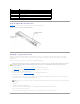
3. Before replacing a fan, check the fan's power cable connection to verify that a loose connection is not the problem. If the problem is not resolved, continue with this procedure. Figure 6-12. Cooling Fan 4. Disconnect the fan power cable from the system board or control panel board. 5. Lift the defective fan straight up out of the power-supply bay or fan bracket. See Figure 6-12. 6. Insert the new fan straight down into the power-supply bay or fan bracket.
Installing a Power Supply 1. 2. To install the replacement power supply, align the stud on the side of the power supply with the corresponding notch in the chassis wall, and then lower the power supply into the chassis. See Figure 6-13. Slide the power supply toward the PDB until the power supply connector is fully seated in the PDB connector. Replacing the System Battery The system battery is a 3.
NOTICE: To avoid damage to the battery connector, you must firmly support the connector while installing or removing a battery. 5. Install the new system battery. See Figure 6-14. a. Support the battery connector by pressing down firmly on the positive side of the connector. b. Hold the battery with the "+" facing up, and slide it under the securing tabs at the positive side of the connector. c. Press the battery straight down into the connector until it snaps into place. 6.
Back to Contents Page Installing Drives Dell™ PowerEdge™ 1750 Systems Installation and Troubleshooting Guide Installing SCSI Hard Drives Installing a CD Drive Installing a Diskette Drive Connecting External SCSI Hard Drives Connecting an External SCSI Tape Drive Configuring the Boot Device Your system features three internal hard-drive bays to accommodate up to three SCSI hard drives. Your system also features two peripheral bays that can be used for an optional CD drive and a 3.5-inch diskette drive.
4. Insert the hard drive into the drive bay. See Figure 7-1. 5. Close the hard-drive handle to lock the drive in place. 6. Replace the front bezel, if it was removed in step 3. 7. If the hard drive is a new drive, run the SCSI Controllers test in the system diagnostics. Removing a SCSI Hard Drive NOTICE: Hot-plug drive installation is not supported for systems without the optional ROMB card. 1. If the system does not have a ROMB installed, shut down the system. 2.
a. b. c. 6. Match the back end of the drive with the back end of the carrier, which has a retention tab. Fit the right edge of the CD drive into the carrier tray, pressing the drive firmly backward against the stop tab near the right rear corner of the carrier. Lower the left side of the drive into the carrier until the drive snaps into place. Slide the drive into the peripheral bay until it is fully inserted. See Figure 7-3. Figure 7-3. Installing a CD Drive 7.
Figure 7-4. Installing a Diskette Drive in a Carrier a. Fit the right edge of the diskette drive into the carrier tray, pressing the drive against the stop tab at the back of the carrier. b. Lower the left edge of the drive into the carrier until the drive snaps into place. c. 6. Attach the end of the ribbon cable labeled "FLOPPY" to the back of the diskette drive, and then insert the cable through the slot in the cable guide at the back of the carrier.
If you are attaching multiple external SCSI devices, daisy-chain the devices using the cables shipped with each device. 4. Reconnect the system to an electrical outlet and turn it on. 5. Connect the external device(s) to electrical outlet(s) and turn them on. 6. Install any required SCSI device drivers. See "Installing and Configuring SCSI Drivers" in the User's Guide. 7. Test the SCSI devices.
Back to Contents Page Getting Help Dell™ PowerEdge™ 1750 Systems Installation and Troubleshooting Guide Technical Assistance Dell Enterprise Training and Certification Problems With Your Order Product Information Returning Items for Warranty Repair or Credit Before You Call Contacting Dell Technical Assistance If you need assistance with a technical problem, perform the following steps: 1. Complete the procedures in "Troubleshooting Your System." 2.
apmarketing@dell.com (for Asian/Pacific countries only) l Electronic Information Service info@dell.com AutoTech Service Dell's automated technical support service—AutoTech—provides recorded answers to the questions most frequently asked by Dell customers about their portable and desktop computer systems. When you call AutoTech, use your touch-tone telephone to select the subjects that correspond to your questions. The AutoTech service is available 24 hours a day, 7 days a week.
Remember to fill out the Diagnostics Checklist. If possible, turn on your system before you call Dell for technical assistance and call from a telephone at or near the computer. You may be asked to type some commands at the keyboard, relay detailed information during operations, or try other troubleshooting steps possible only at the computer system itself. Ensure that the system documentation is available.
Country Code: 61 City Code: 2 Austria (Vienna) International Access Code: 900 Country Code: 43 City Code: 1 Government and Business toll-free: 1-800-633-559 Preferred Accounts Division (PAD) toll-free: 1-800-060-889 Customer Care toll-free: 1-800-819-339 Corporate Sales toll-free: 1-800-808-385 Transaction Sales toll-free: 1-800-808-312 Fax toll-free: 1-800-818-341 Website: support.euro.dell.com E-mail: tech_support_central_europe@dell.
Home and Small Business Preferred Accounts Division toll-free: 800 858 2222 toll-free: 800 858 2062 Large Corporate Accounts GCP toll-free: 800 858 2055 Large Corporate Accounts Key Accounts toll-free: 800 858 2628 Large Corporate Accounts North toll-free: 800 858 2999 Large Corporate Accounts North Government and Education toll-free: 800 858 2955 Large Corporate Accounts East toll-free: 800 858 2020 Large Corporate Accounts East Government and Education toll-free: 800 858 2669 Large Corporate
Germany (Langen) International Access Code: 00 Sales 01 55 94 71 00 Fax 01 55 94 71 01 Website: support.euro.dell.com E-mail: tech_support_central_europe@dell.
Large Corporate Accounts Sales (over 3500 employees) 044-556-3430 Public Sales (government agencies, educational institutions, and medical institutions) 044-556-1469 Global Segment Japan 044-556-3469 Individual User 044-556-1760 Faxbox Service 044-556-3490 Switchboard Korea (Seoul) International Access Code: 001 Country Code: 82 toll-free: 080-200-3800 Sales toll-free: 080-200-3600 Customer Service (Seoul, Korea) toll-free: 080-200-3800 Customer Service (Penang, Malaysia) Fax City Code: 2 L
Home/Small Business Customer Care Relational Customer Care New Zealand International Access Code: 00 Country Code: 64 020 674 55 00 Relational Sales 020 674 50 00 Home/Small Business Sales Fax 020 674 47 75 Relational Sales Fax 020 674 47 50 Switchboard 020 674 50 00 Switchboard Fax 020 674 47 50 E-mail (New Zealand): nz_tech_support@dell.com E-mail (Australia): au_tech_support@dell.
Fax 011 706 0495 Switchboard 011 709 7700 Southeast Asian and Pacific Countries Customer Technical Support, Customer Service, and Sales (Penang, Malaysia) 604 633 4810 Spain (Madrid) Website: support.euro.dell.com City Code: 11 International Access Code: 00 E-mail: support.euro.dell.
Corporate Customer Care 0870 908 0500 Preferred Accounts (500–5000 employees) Customer Care 01344 373 196 Central Government Customer Care 01344 373 193 Local Government & Education Customer Care 01344 373 199 Health Customer Care 01344 373 194 Home and Small Business Sales 0870 907 4000 Corporate/Public Sector Sales 01344 860 456 Uruguay General Support U.S.A.
Back to Contents Page Dell™ PowerEdge™ 1750 Systems Installation and Troubleshooting Guide Notes, Notices, and Cautions Abbreviations and Acronyms Notes, Notices, and Cautions NOTE: A NOTE indicates important information that helps you make better use of your computer. NOTICE: A NOTICE indicates either potential damage to hardware or loss of data and tells you how to avoid the problem. CAUTION: A CAUTION indicates a potential for property damage, personal injury, or death.