
Owners Manual
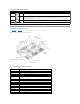
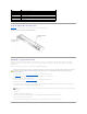

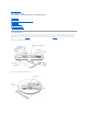

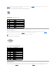
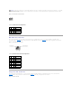
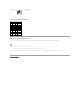

Table A-1.SystemBoardJumperSettings
System Board Connectors
See FigureA-3 and TableA-2 for the descriptions and locations of the system board connectors.
Figure A-3. System Board Connectors and Sockets
Table A-2.SystemBoardConnectorsandSockets
Jumper
Setting
Description
PASSWD
(default)
The password feature is enabled.
The password feature is disabled.
NVRAM_CLR
(default)
The configuration settings are retained at system boot.
The configuration settings are cleared at next system boot. (If the configuration settings become corrupted to the point
where the system will not boot, install the jumper plug and boot the system. Remove the jumper before restoring the
configuration information.)
RSVD
Reserved (do not change).
jumpered unjumpered
Connector or Socket
Description
BACKPLANE
SCSI backplane board connector
B1
System battery connector
CYCLOPS
Cable-management arm system status connector
DIMM_1x; DIMM_2x
Memory module sockets
EMBEDDED_REMOTE_
ASSISTANT
Connector for optional RAC
EMP_NIC
RAC Ethernet port connector
ETHERNET_n
NIC connectors (2)
FANn
Cooling fan power connectors (six on system board; one on control panel assembly)
FRONT_PANEL
System control panel connector
KYBD
Keyboard connectors
MOUSE
Mouse connector
PCIn
PCI riser board connector
PROCESSOR 1
Microprocessor socket 1
PROCESSOR 2
Microprocessor socket 2
PS_PWR
System board power connector