
Owners Manual


TableB-1 shows the icons used to label the connectors on the system.
Table B-1.I/OConnectorIcon
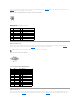
Serial Connector
Serial connectors support devices such as external modems, printers, and mice that require serial data transmission. The serial connector uses a 9-pin D-
subminiature connector.
Serial Connector Autoconfiguration
The default designation of the integrated serial connector is COM1. When you add an expansion card containing a serial connector that has the same
designation as the integrated connector, the system's autoconfiguration feature remaps (reassigns) the integrated serial connector to the next available
designation. Both the new and the remapped COM connectors share the same IRQ setting. COM1 and COM3 share IRQ4, while COM2 and COM4 share IRQ3.
Before adding a card that remaps the COM connectors, check the documentation that came with the software to make sure that the software can
accommodate the new COM connector designation.
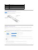
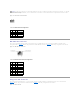
FigureB-3 illustrates the pin numbers for the serial connector and TableB-2 defines the pin assignments for the connector.
Figure B-3. Serial Connector Pin Numbers
Table B-2.SerialConnectorPinAssignments
PS/2-Compatible Keyboard and Mouse Connectors
Icon
Connector
Serial connector
Mouse connector
Keyboard connector
Video connector
USB connector
NIC connector
RAC Ethernet connector
NOTE: If two COM connectors share an IRQ setting, you may not be able to use them both at the same time. In addition, if you install one or more
expansion cards with serial connectors designated as COM1 and COM3, the integrated serial connector is disabled.
Pin
Signal
I/O
Definition
1
DCD
I
Data carrier detect
2
SIN
I
Serial input
3
SOUT
O
Serial output
4
DTR
O
Data terminal ready
5
GND
N/A
Signal ground
6
DSR
I
Data set ready
7
RTS
O
Request to send
8
CTS
I
Clear to send
9
RI
I
Ring indicator
Shell
N/A
N/A
Chassis ground