Dell™ PowerEdge™ 19x0 and 29x0 Systems Installing a SATA Optical Drive
Notes, Cautions, and Warnings NOTE: A NOTE indicates important information that helps you make better use of your computer. CAUTION: A CAUTION indicates potential damage to hardware or loss of data if instructions are not followed. WARNING: A WARNING indicates a potential for property damage, personal injury, or death. ____________________ Information in this document is subject to change without notice. © 2008 Dell Inc. All rights reserved.
Installing a SATA Optical Drive These instructions apply to Dell™ PowerEdge™ systems to which a SATA optical drive is being added, or in which an existing PATA or IDE optical drive is being replaced by a SATA optical drive. WARNING: Only trained service technicians are authorized to remove the system cover and access any of the components inside the system. Before you begin this procedure, review the safety instructions that came with the system.
Preparing the Optical Drive Tray – PowerEdge 2970, 2950, and 1950 For PowerEdge 2970 and 2950 systems, the optical drive tray that shipped with the system is used for the SATA optical drive. If you are replacing an existing IDE optical drive, you must remove the old drive and interposer card from the drive carrier and install the new SATA drive in the same carrier. On PowerEdge 1950 systems, the existing optical drive tray must be replaced with the drive tray provided with the SATA drive installation kit.
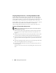
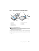
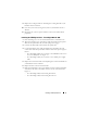
Figure 1-1. Replacing the Optical Drive in a PowerEdge 2950 or 2970 System 3 2 4 5 1 6 7 1 optical drive 2 interposer release latch 3 interposer 4 SATA cable 5 SATA power cable 6 carrier latch 7 optical drive carrier Replacing a PowerEdge 1950 Optical Drive NOTE: The replacement drive tray provided in the installation kit must be used with PowerEdge 1950 systems. If you are replacing an existing optical drive, do not reuse the interposer board attached to the old drive.
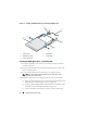
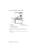
Figure 1-2. Installing a SATA Optical Drive in a PowerEdge 1950 Drive Tray 2 3 1 4 5 1 optical drive 2 SATA cable 3 SATA power cable 4 carrier latch 5 optical drive carrier Installing the SATA Optical Drive – PowerEdge 1950 1 Insert the optical drive tray into the system until it is fully inserted and locked into position. 2 Connect the SATA cable (the end with the branching power cable) to the back of the optical drive. 3 Connect the branching power cable to the power supply connector.
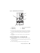
Figure 1-3. SATA Cable Routing in the PowerEdge 1950 2 3 1 4 6 5 1 SATA data cable 2 SATA_A connector on system board 3 chipset shroud 4 system fans 5 SATA power cable 6 optical drive 5 Reinstall the SAS controller daughter card and reconnect the SAS cable. See "SAS Controller Daughter Card" in your Hardware Owner’s Manual. 6 Close the system. See "Closing the System" in your Hardware Owner’s Manual. 7 Reconnect the system to power and turn on the system and attached peripherals.
4 Remove the cooling shroud. See "Removing the Cooling Shroud" in your Hardware Owner’s Manual. 5 Remove the cable retention bracket from the right interior wall of the chassis by pushing the blue release latch and sliding the bracket toward the front of the system until the bracket detaches from the chassis slots. 6 Route the SATA cable in the cable channel in the right wall of the chassis and replace the cable retention bracket over the cable. See Figure 1-4.
Replace the cooling shroud. See "Installing the Cooling Shroud" in your Hardware Owner’s Manual. 10 Close the system. See "Closing the System" in your Hardware Owner’s Manual. 11 Reconnect the system to power and turn on the system and attached peripherals. Installing the SATA Optical Drive – PowerEdge 2900 and 1900 1 If the mounting screws are not attached to the drive, install them now.
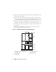
Figure 1-5. SATA Cable Routing in a PowerEdge 2900 or 1900 3 4 2 5 1 1 optical drive 2 SATA power cable 3 SATA data cable 4 SATA connector on system board 5 SATA power connector on SAS backplane (PowerEdge 2900 only) 8 Reconnect the cables to the SAS controller daughter card. 9 Close the system. See "Closing the System" in your Hardware Owner’s Manual. 10 Reconnect the system to power and turn on the system and attached peripherals.